• Chinese Optics Letters
  • Vol. 21, Issue 7, 073201 (2023)
Wei Li1、2, Xiao Wang2、*, Yanlei Zuo2、**, Yilin Hong1, Bilong Hu2, Zhaohui Wu2, Jie Mu2, Kainan Zhou2, and Xiaoming Zeng2
Author Affiliations
  • 1National Synchrotron Radiation Laboratory, University of Science and Technology of China, Hefei 230026, China
  • 2Laser Fusion Research Center, China Academy of Engineering Physics, Mianyang 621900, China
  • show less
    DOI: 10.3788/COL202321.073201 Cite this Article Set citation alerts
    Wei Li, Xiao Wang, Yanlei Zuo, Yilin Hong, Bilong Hu, Zhaohui Wu, Jie Mu, Kainan Zhou, Xiaoming Zeng, "A cylindrical Öffner stretcher based on ternary reflector for femtosecond petawatt-level laser system," Chin.Opt.Lett. 21, 073201 (2023) Copy Citation Text show less
    Top and side views of the COSTER. G1 and G2, gratings; CCM1 and CCM2, concave and convex cylindrical mirrors; M, flat mirror; TR, ternary reflector, consisting of three flat mirrors; RM, roof mirror. As shown in the dashed box, compared with the RM, the TR does not change the spatial chirp direction of the output laser. The green font in the side view indicates which pass of the laser goes through the COSTER.
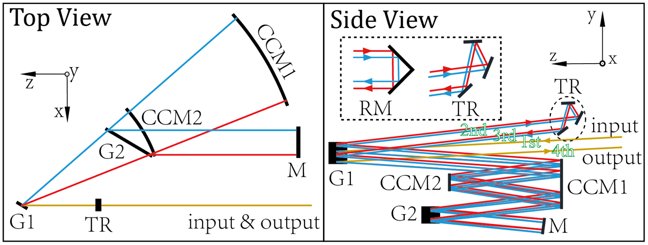
    Fig. 1. Top and side views of the COSTER. G1 and G2, gratings; CCM1 and CCM2, concave and convex cylindrical mirrors; M, flat mirror; TR, ternary reflector, consisting of three flat mirrors; RM, roof mirror. As shown in the dashed box, compared with the RM, the TR does not change the spatial chirp direction of the output laser. The green font in the side view indicates which pass of the laser goes through the COSTER.
    Top and side views of double-grating Öffner stretcher. G1 and G2, gratings; CM1 and CM2, concave and convex mirrors; RM1 and RM2, roof mirrors. The off-axis aberration of the concave mirror is shown in the dashed box. L, off-axis distance; f, the focal length of the concave mirror.
    Fig. 2. Top and side views of double-grating Öffner stretcher. G1 and G2, gratings; CM1 and CM2, concave and convex mirrors; RM1 and RM2, roof mirrors. The off-axis aberration of the concave mirror is shown in the dashed box. L, off-axis distance; f, the focal length of the concave mirror.
    Spot diagram of the output laser of the double-grating Öffner stretcher. (a) The laser propagates 1 m after one pass through the stretcher; (b) the laser propagates 10 m after one pass through the stretcher.
    Fig. 3. Spot diagram of the output laser of the double-grating Öffner stretcher. (a) The laser propagates 1 m after one pass through the stretcher; (b) the laser propagates 10 m after one pass through the stretcher.
    Spot diagram of the output laser of COSTER. (a) The laser propagates 1 m after one pass through the COSTER; (b) the laser propagates 10 m after one pass through the COSTER.
    Fig. 4. Spot diagram of the output laser of COSTER. (a) The laser propagates 1 m after one pass through the COSTER; (b) the laser propagates 10 m after one pass through the COSTER.
    Calculation model of the temporal contrast of the laser passing through a stretcher. (a) Schematic of the zero-dispersion stretcher. G1 and G2, gratings; C1 and C2, concave and convex (cylindrical) mirrors; F, focusing element; f, focal length of the concave (cylindrical) mirror; (b) simulated surface profile and beam locations of different spectral component (ω1–n); (c) scalar diffraction calculation model for a broadband laser. Sampling along the ω axis of the broadband laser field (Ein (x,y,ω)), then calculating the output field of each spectral component (Eout (x,y,ω)) based on the scalar diffraction theory, finally using inverse discrete Fourier transform (IDFT) to obtain the output field (Eout (x,y,t)).
    Fig. 5. Calculation model of the temporal contrast of the laser passing through a stretcher. (a) Schematic of the zero-dispersion stretcher. G1 and G2, gratings; C1 and C2, concave and convex (cylindrical) mirrors; F, focusing element; f, focal length of the concave (cylindrical) mirror; (b) simulated surface profile and beam locations of different spectral component (ω1–n); (c) scalar diffraction calculation model for a broadband laser. Sampling along the ω axis of the broadband laser field (Ein (x,y,ω)), then calculating the output field of each spectral component (Eout (x,y,ω)) based on the scalar diffraction theory, finally using inverse discrete Fourier transform (IDFT) to obtain the output field (Eout (x,y,t)).
    (a) Partial surface profile used in the simulation; (b) 1D PSD of surface profile. The red dashed line indicates the PSD criterion line of the NIF, and the blue solid line indicates the average 1D PSD of the surface profile.
    Fig. 6. (a) Partial surface profile used in the simulation; (b) 1D PSD of surface profile. The red dashed line indicates the PSD criterion line of the NIF, and the blue solid line indicates the average 1D PSD of the surface profile.
    Far-field on-axis spectral phase of the output laser. COSTER and concave mirror, with the surface profile distortion of concave cylindrical mirror in the COSTER (blue line); COSTER and convex mirror, with the surface profile distortion of convex cylindrical mirror in the COSTER (orange line); SOS and concave mirror, with the surface profile distortion of concave mirror in SOS (yellow line); SOS and convex mirror, with the surface profile distortion of the convex mirror in the SOS (purple line).
    Fig. 7. Far-field on-axis spectral phase of the output laser. COSTER and concave mirror, with the surface profile distortion of concave cylindrical mirror in the COSTER (blue line); COSTER and convex mirror, with the surface profile distortion of convex cylindrical mirror in the COSTER (orange line); SOS and concave mirror, with the surface profile distortion of concave mirror in SOS (yellow line); SOS and convex mirror, with the surface profile distortion of the convex mirror in the SOS (purple line).
    Normalized temporal intensity in the far-field. (a) With the surface profile distortion of the concave (cylindrical) mirror; (b) with the surface profile distortion of the convex (cylindrical) mirror.
    Fig. 8. Normalized temporal intensity in the far-field. (a) With the surface profile distortion of the concave (cylindrical) mirror; (b) with the surface profile distortion of the convex (cylindrical) mirror.
    Normalized 3D spatial-temporal intensity distribution in the far field. (a) and (c) Surface profile distortion of the concave (cylindrical) mirror in the SOS and the COSTER, respectively; (b) and (d) surface profile distortion of the convex (cylindrical) mirror in the SOS and the COSTER, respectively.
    Fig. 9. Normalized 3D spatial-temporal intensity distribution in the far field. (a) and (c) Surface profile distortion of the concave (cylindrical) mirror in the SOS and the COSTER, respectively; (b) and (d) surface profile distortion of the convex (cylindrical) mirror in the SOS and the COSTER, respectively.
    ItemValue
    Radius of concave (cylindrical) mirror1200 mm
    Radius of convex (cylindrical) mirror600 mm
    Grating line density1480 lines/mm
    Distance between the two gratings500 mm
    Incident angle60°
    Diameter of the laser beam10 mm
    Central wavelength900 nm
    Table 1. Parameters of the COSTER/SOS and the Input Laser
    Wei Li, Xiao Wang, Yanlei Zuo, Yilin Hong, Bilong Hu, Zhaohui Wu, Jie Mu, Kainan Zhou, Xiaoming Zeng, "A cylindrical Öffner stretcher based on ternary reflector for femtosecond petawatt-level laser system," Chin.Opt.Lett. 21, 073201 (2023)
    Download Citation