
Wei Li, Xiao Wang, Yanlei Zuo, Yilin Hong, Bilong Hu, Zhaohui Wu, Jie Mu, Kainan Zhou, Xiaoming Zeng, "A cylindrical Öffner stretcher based on ternary reflector for femtosecond petawatt-level laser system," Chin. Opt. Lett. 21, 073201 (2023)
- Chinese Optics Letters
- Vol. 21, Issue 7, 073201 (2023)
Abstract
1. Introduction
Recently, an unprecedented high peak power laser has been created in the laboratory based on chirped pulse amplification (CPA). Now the focused intensity can reach a level of
The most commonly used stretchers in CPA laser systems include Martinez[3] and Öffner[4] configurations. The Martinez stretchers have obvious chromatic aberration, so they are not suitable for use in an ultrawideband laser systems. The Öffner stretchers include single-grating and double-grating configurations. Compared with the single-grating configuration, the laser pulse out of the double-grating stretcher has smaller aberration, so the latter has been used in some 10-petawatt-level laser facilities, such as the Apollon laser facility[5] and the Shanghai Superintense Ultrafast Laser Facility (SULF)[6]. In the petawatt-level laser facility, in order to increase the stretching quantity for the femtosecond pulse to better match the nanosecond-level pump pulse and reduce the volume and cost of the stretcher, it is necessary to adopt a multipass design for the stretcher. However, the analysis in this paper shows that the double-grating Öffner stretchers have significant off-axis aberration in the multipass configuration, which would cause spatiotemporal coupling distortion of the output laser.
In addition, many studies suggest that the far-field spectral phase noise in stretcher was the sources of tens-of-picoseconds’ intensity pedestal in the CPA laser systems[5,7]. In order to avoid preionization of the experimental target, the intensity of the noise or pre-pulses should not exceed the level of
Sign up for Chinese Optics Letters TOC. Get the latest issue of Chinese Optics Letters delivered right to you!Sign up now
In order to improve the temporal contrast, Tang et al. designed a stretcher without a far-field optical component for the Gemini laser system[10]. Lu et al. presented a novel stretcher based on two concave mirrors, which also has no optical component on the focal plane[11,12]. However, these kinds of stretchers have larger chromatic aberration than the Öffner stretcher. Bromage et al. designed a cylindrical Öffner stretcher[13,14] that improves the temporal contrast while retaining the aberration-free nature of the Öffner structure. However, the output laser of this stretcher has spatial chirp.
In this paper, a cylindrical Öffner stretcher based on ternary reflector (COSTER) is proposed and analyzed. The COSTER has no off-axis aberration, even in the multipass configuration, and it has no far-field optical element, which allows higher far-field on-axis temporal contrast of the output laser. In addition, the COSTER supports higher pulse energy because each spectral component is focused to a line on the cylindrical convex mirror instead of being focused to a point. The COSTER is better than the traditional double-grating Öffner stretchers in many ways, and it is scheduled to be used in the 10-petawatt-level laser facility of the Photonics Science Center of Zhongshan.
2. Structure of the COSTER
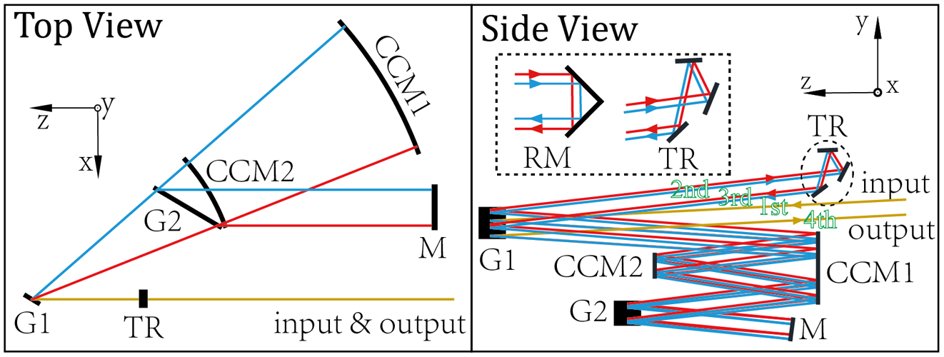
Figure 1 shows the structure of the COSTER, in which the laser transmits four times. In the first pass, the laser is incident to grating G1 at an angle of 4.3° with the
![]()
Figure 1.Top and side views of the COSTER. G1 and G2, gratings; CCM1 and CCM2, concave and convex cylindrical mirrors; M, flat mirror; TR, ternary reflector, consisting of three flat mirrors; RM, roof mirror. As shown in the dashed box, compared with the RM, the TR does not change the spatial chirp direction of the output laser. The green font in the side view indicates which pass of the laser goes through the COSTER.
In addition, since each spectral component in the COSTER is line-focused on the convex cylindrical mirror rather than point-focused in a traditional Öffner stretcher, the COSTER will support a higher pulse energy at a limited damage threshold of the optical elements.
3. Performance Analysis of the COSTER
3.1. Analysis of aberrations
The traditional double-grating spherical Öffner stretcher (SOS) is generally considered to be aberration-free. However, it is not the case in a multipass configuration. Figure 2 shows the structure of a four-pass double-grating SOS. In order to achieve multipass, the laser beam must propagate off-axis. In this case, off-axis aberration is unavoidable. As shown in the dashed box in Fig. 2, the larger the off-axis distance L, the farther away the reflected laser is from the focus.
![]()
Figure 2.Top and side views of double-grating Öffner stretcher. G1 and G2, gratings; CM1 and CM2, concave and convex mirrors; RM1 and RM2, roof mirrors. The off-axis aberration of the concave mirror is shown in the dashed box. L, off-axis distance; f, the focal length of the concave mirror.
The off-axis aberration of a traditional SOS will cause frequency-dependent spatial distortion of the output laser. We simulated the transmission of laser in the stretcher using the ray-tracing[15] method, where the 3D spatial diffraction calculation of the grating is referred to Ref. [16]. In this simulation, the off-axis distance of the input laser and the second/third pass laser in the
![]()
Figure 3.Spot diagram of the output laser of the double-grating Öffner stretcher. (a) The laser propagates 1 m after one pass through the stretcher; (b) the laser propagates 10 m after one pass through the stretcher.
| Item | Value |
|---|---|
| Radius of concave (cylindrical) mirror | 1200 mm |
| Radius of convex (cylindrical) mirror | 600 mm |
| Grating line density | 1480 lines/mm |
| Distance between the two gratings | 500 mm |
| Incident angle | 60° |
| Diameter of the laser beam | 10 mm |
| Central wavelength | 900 nm |
Table 1. Parameters of the COSTER/SOS and the Input Laser
The spot diagram of the output laser of COSTER is calculated under the same conditions (shown in Table 1), and the results are shown in Fig. 4. It can be seen that the spot diagram of each spectral component has no distortion, and the shape of the spot diagram almost does not change with the transmission distance. This indicates that the COSTER effectively eliminates aberrations in the multipass configuration because every pass is transmitted within the radius planes of CCM1 and CCM2.
![]()
Figure 4.Spot diagram of the output laser of COSTER. (a) The laser propagates 1 m after one pass through the COSTER; (b) the laser propagates 10 m after one pass through the COSTER.
3.2. Analysis of far-field temporal contrast
Compared with the SOS, another advantage of the COSTER is that the output laser has less far-field spectral phase noise and higher temporal contrast. In an SOS, different spectral components are focused on the surface of convex mirror, which is a far-field element. But in COSTER, the laser on the surface of convex cylindrical mirror is only focused in one direction, so it is not a strict far-field optical element. The surface profile distortion of convex cylindrical mirror in COSTER has less effect on the far-field on-axis spectral phase, which allows higher far-field on-axis temporal contrast. To prove that, we simulated the impact of surface profile distortion of the concave/convex (cylindrical) mirrors on the far-field temporal contrast. The model used for the simulation is shown in Fig. 5. Figure 5(a) shows the schematic of a zero-dispersion stretcher, in which
![]()
Figure 5.Calculation model of the temporal contrast of the laser passing through a stretcher. (a) Schematic of the zero-dispersion stretcher. G1 and G2, gratings; C1 and C2, concave and convex (cylindrical) mirrors; F, focusing element; f, focal length of the concave (cylindrical) mirror; (b) simulated surface profile and beam locations of different spectral component (ω1–n); (c) scalar diffraction calculation model for a broadband laser. Sampling along the ω axis of the broadband laser field (Ein (x,y,ω)), then calculating the output field of each spectral component (Eout (x,y,ω)) based on the scalar diffraction theory, finally using inverse discrete Fourier transform (IDFT) to obtain the output field (Eout (x,y,t)).
Figure 5(c) shows the scalar diffraction calculation model for a broadband laser, which could be used to calculate the influence of the surface profile distortion of various optics on the laser field. When the laser is reflected by the optical elements, the surface profile distortion will be mapped to the wavefront of the laser according to Eq. (3),
The effect of mid-frequency surface profile distortion (spatial period range: 0.12–33 mm) of the concave/convex (cylindrical) mirror is considered in this simulation. The simulated surface profile obeys the power spectrum density (PSD) criterion line of the large aperture optics defined by the National Ignition Facility (NIF)[17], which is given by
The partial surface profile used in the simulation is shown in Fig. 6(a). The 1D PSD of the simulated surface profile (blue solid line) and the PSD criterion line of NIF (red dashed line) are shown in Fig. 6(b).
![]()
Figure 6.(a) Partial surface profile used in the simulation; (b) 1D PSD of surface profile. The red dashed line indicates the PSD criterion line of the NIF, and the blue solid line indicates the average 1D PSD of the surface profile.
The far-field on-axis spectral phase (Fig. 7) and temporal contrast (Fig. 8) of the output laser of the SOS and the COSTER are simulated under the same surface profile conditions. Figure 7 shows that the surface profile distortion of the concave (cylindrical) mirror in the SOS and the COSTER will cause nearly the same distortions of far-field on-axis spectral phase. In contrast, the surface profile distortion of convex (cylindrical) mirror will cause obvious high-frequency noise of the far-field on-axis spectral phase, and the spectral phase of the COSTER is smoother than that of the SOS.
![]()
Figure 7.Far-field on-axis spectral phase of the output laser. COSTER and concave mirror, with the surface profile distortion of concave cylindrical mirror in the COSTER (blue line); COSTER and convex mirror, with the surface profile distortion of convex cylindrical mirror in the COSTER (orange line); SOS and concave mirror, with the surface profile distortion of concave mirror in SOS (yellow line); SOS and convex mirror, with the surface profile distortion of the convex mirror in the SOS (purple line).
![]()
Figure 8.Normalized temporal intensity in the far-field. (a) With the surface profile distortion of the concave (cylindrical) mirror; (b) with the surface profile distortion of the convex (cylindrical) mirror.
Figure 8 shows the far-field on-axis temporal contrast of the output laser. Figure 8(a) shows the far-field on-axis temporal intensity of the output laser when the surface profile distortion of the concave (cylindrical) mirror is included. In this case, the two kinds of stretchers have the same far-field on-axis temporal contrast. However, as shown in Fig. 8(b), the surface profile distortion of the convex (cylindrical) mirror has a greater effect on the far-field on-axis temporal contrast. And compared with the SOS, the output laser of the COSTER has a higher far-field on-axis temporal contrast, and its signal-to-noise ratio at 20 ps is
Based on Figs. 7 and 8, it can be seen that the surface profile distortion of the convex (cylindrical) mirror is the main factor that leads to the high-frequency noise of the far-field on-axis spectral phase and the reduction of the far-field on-axis temporal contrast. In addition, compared with the SOS, the output laser of the COSTER has higher far-field on-axis temporal contrast.
In fact, the far-field intensity noise is spatiotemporally coupled[9]. Figure 9 is the simulation result of the 3D spatial-temporal distribution of far-field intensity, which can explain why using COSTER can enhance the far-field on-axis contrast. As shown in Figs. 9(a) and 9(c), the noise produced by the concave (cylindrical) mirror in the SOS and the COSTER will exhibit similar spatial-temporal coupling characteristics. The noise of the far field is dispersed in space, so it does not have a significant effect on the far-field on-axis contrast. However, as shown in Fig. 9(b), the noise generated by the concave mirror in the SOS is concentrated at the place of
![]()
Figure 9.Normalized 3D spatial-temporal intensity distribution in the far field. (a) and (c) Surface profile distortion of the concave (cylindrical) mirror in the SOS and the COSTER, respectively; (b) and (d) surface profile distortion of the convex (cylindrical) mirror in the SOS and the COSTER, respectively.
4. Conclusion
In conclusion, a novel stretcher COSTER was proposed and analyzed. The aberration of the COSTER was analyzed by ray tracing, and the far-field temporal contrast of its output laser was calculated based on scalar diffraction theory. The analysis results show that compared with the traditional double-grating SOS, the COSTER is aberration-free, even in a multipass configuration. And because there is no far-field optical element in the COSTER, the far-field on-axis temporal contrast at 20 ps is
References
[10] Y. Tang, C. Hooker, O. Chekhlov, S. Hawkes, J. Collier, P. P. Rajeev. A novel stretcher for contrast enhancement in CPA lasers. Advanced Solid State Lasers, OSA Technical Digest, ATu2A.41(2014).
[13] J. Bromage, M. Millecchia, J. Bunkenburg, R. K. Jungquist, C. Dorrer, J. D. Zuegel. A cylindrical Öffner stretcher for reduced chromatic aberrations and improved temporal contrast. Conference on Lasers and Electro-Optics, CM4D.4(2012).
[17] C. R. Wolfe, J. K. Lawson. Characterization of large aperture optical wavefronts using the power spectral density function. Optical Fabrication and Testing Technical Digest Series, OWB.2(1996).


Set citation alerts for the article
Please enter your email address

© Copyright 2018-2021 | Chinese Laser Press. All Rights Reserved 沪ICP备15018463号-20