• Laser & Optoelectronics Progress
  • Vol. 58, Issue 13, 1306017 (2021)
Yi Jiang* and Shuhuan Zhang
Author Affiliations
  • Key Laboratory of Photonic Information Technology, Ministry of Industry and Information Technology, School of Optics and Photonics, Beijing Institute of Technology, Beijing 100081, China
  • show less
    DOI: 10.3788/LOP202158.1306017 Cite this Article Set citation alerts
    Yi Jiang, Shuhuan Zhang. Research Progress on Fiber Optical Laser Interferometry in Signal Demodulation of EFPI Sensor[J]. Laser & Optoelectronics Progress, 2021, 58(13): 1306017 Copy Citation Text show less
    Schematic diagram of interference based on Fabry-Perot sensor
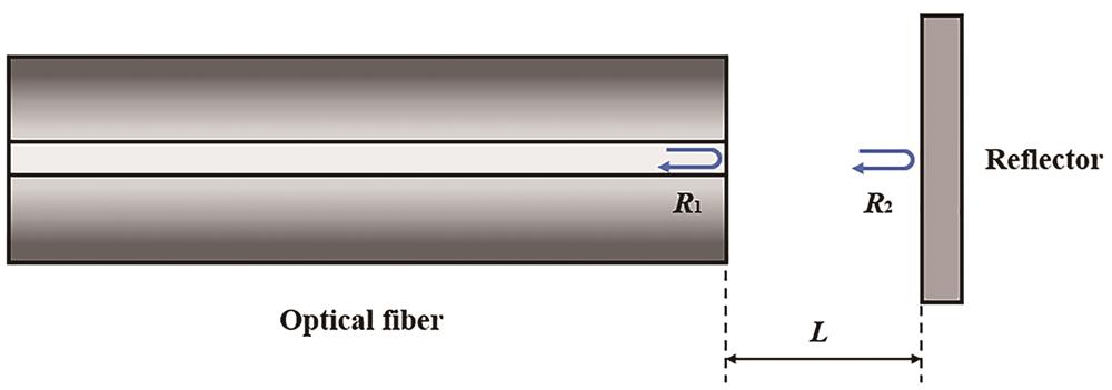
    Fig. 1. Schematic diagram of interference based on Fabry-Perot sensor
    Orthogonal working point and linear interval[24]
    Fig. 2. Orthogonal working point and linear interval[24]
    Static working point stabilization system[1]
    Fig. 3. Static working point stabilization system[1]
    Schematic diagram of EFPI sensor system based on PGC demodulation principle
    Fig. 4. Schematic diagram of EFPI sensor system based on PGC demodulation principle
    Schematic diagram of PMDI-PGC demodulation system[26]
    Fig. 5. Schematic diagram of PMDI-PGC demodulation system[26]
    Schematic diagram of PGC-AD-DSM demodulation algorithm[27]
    Fig. 6. Schematic diagram of PGC-AD-DSM demodulation algorithm[27]
    Schematic diagram of symmetrical demodulation method based on 3×3 coupler[1]
    Fig. 7. Schematic diagram of symmetrical demodulation method based on 3×3 coupler[1]
    Experimental setup for interrogating an EFPI by using a three-wavelength method[29]
    Fig. 8. Experimental setup for interrogating an EFPI by using a three-wavelength method[29]
    Dual-wavelength passive quadrature demodulation system[30]
    Fig. 9. Dual-wavelength passive quadrature demodulation system[30]
    Schematic diagram of dual-wavelength orthogonal demodulation algorithm
    Fig. 10. Schematic diagram of dual-wavelength orthogonal demodulation algorithm
    Schematic diagram of dual-wavelength quadrature phase compensation demodulation algorithm
    Fig. 11. Schematic diagram of dual-wavelength quadrature phase compensation demodulation algorithm
    Schematic diagram of dual-wavelength direct current compensation laser interference demodulation algorithm
    Fig. 12. Schematic diagram of dual-wavelength direct current compensation laser interference demodulation algorithm
    Experimental results of the EFPI with a cavity length of 129.946 μm at 1 kHz[34]
    Fig. 13. Experimental results of the EFPI with a cavity length of 129.946 μm at 1 kHz34
    Schematic diagram of three-wavelength passive demodulation laser interference system[35]
    Fig. 14. Schematic diagram of three-wavelength passive demodulation laser interference system[35]
    Schematic diagram of three-wavelength passive demodulation laser interference algorithm
    Fig. 15. Schematic diagram of three-wavelength passive demodulation laser interference algorithm
    Schematic diagram of experimental results of three-wavelength passive demodulation laser interference[35]
    Fig. 16. Schematic diagram of experimental results of three-wavelength passive demodulation laser interference35
    Schematic diagram of phase shift demodulation algorithm
    Fig. 17. Schematic diagram of phase shift demodulation algorithm
    Schematic diagram of the experimental results of phase-shift demodulation[37]
    Fig. 18. Schematic diagram of the experimental results of phase-shift demodulation37
    Schematic diagram of three-wavelength symmetric demodulation algorithm
    Fig. 19. Schematic diagram of three-wavelength symmetric demodulation algorithm
    Demodulation results. (a) Output signal when the cavity length is changed from 301.252 μm to 264.427 μm; (b)‒(d) enlarged images of areas indicated by the solid boxes in Fig. 20(a)[38]
    Fig. 20. Demodulation results. (a) Output signal when the cavity length is changed from 301.252 μm to 264.427 μm; (b)‒(d) enlarged images of areas indicated by the solid boxes in Fig. 20(a)38
    Demodulation methodDemodulation conditionDemodulation ideaSolved problem
    Dual-wavelength DC compensation laser interferometryEFPI cavity length and source wavelength are knownDC compensation,phase compensation, signal recoveryDual-wavelength demodulation method can be used to interrogate EFPIs with any cavity length and any phase modulation
    Three-wavelength passive demodulation laser interferometryEFPI cavity length and source wavelength are knownDC compensation,phase compensation, signal recoveryDC component is compensated online, the EFPI demodulation with any cavity length and any phase modulation can be realized
    Three-wavelength phase shift demodulation laser interferometryEFPI cavity length and source wavelength are knownInterferometric signal,tangent of the signal,signal recoveryDC and phase compensation are eliminated directly; the EFPI demodulation with any cavity length and any phase modulation can be realized
    Three-wavelength symmetric demodulation laser interferometryTwo interferometric signals are symmetrical about the third interferometric signalInterferometric signal,tangent of the signal,signal recoveryUnder the condition of unknown cavity length, it can be used to interrogate EFPIs with any cavity length and any phase modulation
    Table 1. Comparison of four different demodulation methods
    Yi Jiang, Shuhuan Zhang. Research Progress on Fiber Optical Laser Interferometry in Signal Demodulation of EFPI Sensor[J]. Laser & Optoelectronics Progress, 2021, 58(13): 1306017
    Download Citation