
Yunfei Lei, Jinyuan Liu, Houzhi Cai, Junkun Huang, Yong Wang, Pokun Deng. Imaging Performance of Double-Lens Pulse-Dilation Framing Camera[J]. Laser & Optoelectronics Progress, 2022, 59(18): 1832001
- Laser & Optoelectronics Progress
- Vol. 59, Issue 18, 1832001 (2022)
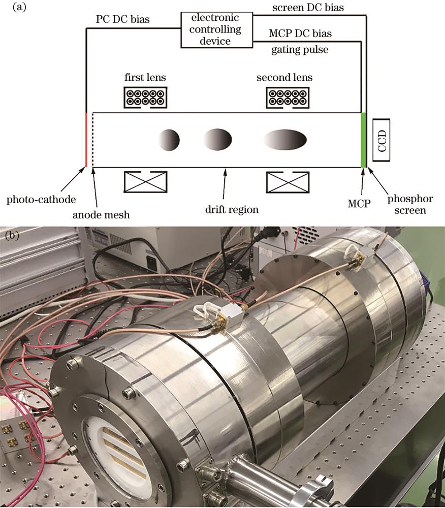
Fig. 1. Pulse-dilation framing camera. (a) Schematic diagram; (b) photograph
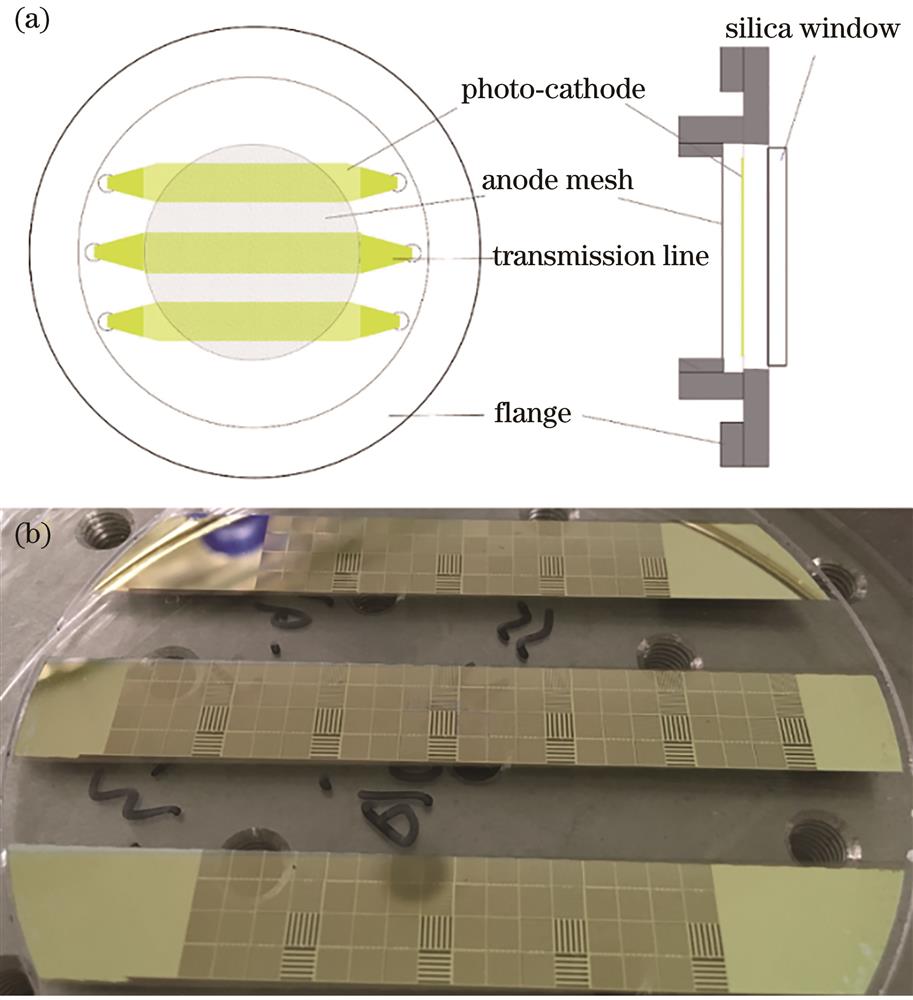
Fig. 2. Transmission photo-cathode. (a) Schematic diagram; (b) photograph
Fig. 3. Schematic of microchannel plate
Fig. 4. Magnetic lens and magnetic field strength on the axis. (a) Schematic of magnetic lens; (b) magnetic field distribution in drift region
Fig. 5. Diagram of experimental setup and grating structure. (a) Experimental setup of the spatial resolution measurement; (b) grating structure of the PC
Fig. 6. Middle PC images and corresponding grating intensity. (a) Middle PC image with double magnetic lenses; (b) middle PC image with single magnetic lens; (c) corresponding grating intensity of double magnetic lenses; (d) corresponding grating intensity of single magnetic lens
Fig. 7. Modulation of the grating versus off-axis distance. (a) Modulation curve of the single lens; (b) modulation curve of the double lenses
Fig. 8. Electron trajectory and field curvature. (a) Simulated electron trajectory of double magnetic lenses; (b) fitting of the field curvature
Fig. 9. Curved surface of image field and corresponding parameter relationship. (a) Curved surface of image field under different currents; (b) corresponding relationship between object image distance and coil current
Fig. 10. Electron dispersion of imaging points on the receiving surface at different off-axis distances. (a) On-axis imaging point; (b) imaging point at 8-mm off-axis; (c) imaging point at 20-mm off-axis
Fig. 11. Diagram of the astigmatism
Fig. 12. Middle PC images with different coil currents in second lens
Fig. 13. Tangential and sagittal spatial resolutions versus the coil current in second lens. (a) Imaging point at 4-mm off-axis; (b) imaging point at 8-mm off-axis; (c) imaging point at 15-mm off-axis; (d) imaging point at 20-mm off-axis

Set citation alerts for the article
Please enter your email address
© Copyright 2018-2021 | Chinese Laser Press. All Rights Reserved 沪ICP备15018463号-20