
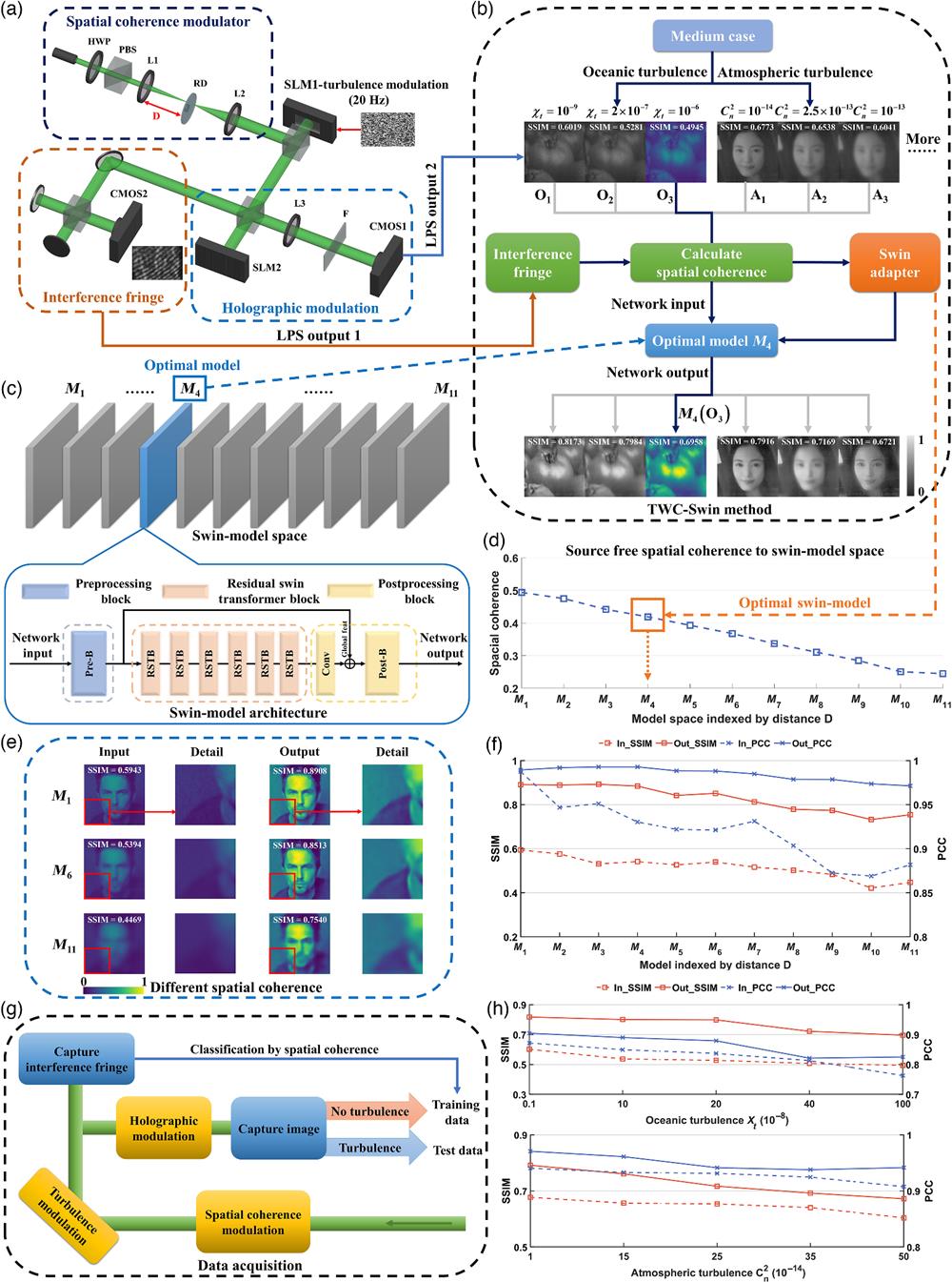
Xin Tong, Renjun Xu, Pengfei Xu, Zishuai Zeng, Shuxi Liu, Daomu Zhao, "Harnessing the magic of light: spatial coherence instructed swin transformer for universal holographic imaging," Adv. Photon. 5, 066003 (2023)
- Advanced Photonics
- Vol. 5, Issue 6, 066003 (2023)


Set citation alerts for the article
Please enter your email address

© Copyright 2018-2021 | Chinese Laser Press. All Rights Reserved 沪ICP备15018463号-20