
Shuiying Xiang, Yanan Han, Ziwei Song, Xingxing Guo, Yahui Zhang, Zhenxing Ren, Suhong Wang, Yuanting Ma, Weiwen Zou, Bowen Ma, Shaofu Xu, Jianji Dong, Hailong Zhou, Quansheng Ren, Tao Deng, Yan Liu, Genquan Han, Yue Hao. A review: Photonics devices, architectures, and algorithms for optical neural computing[J]. Journal of Semiconductors, 2021, 42(2): 023105
- Journal of Semiconductors
- Vol. 42, Issue 2, 023105 (2021)
Abstract
1. Introduction
In the past few decades, the computing capability of conventional digital computers based on complementary metal oxide semiconductor (CMOS) transistors has been increased greatly as predicted by Gordon Moore[
The human brain, which is believed to be the most complex intelligent system in the universe, exhibits ultralow power consumption, massive parallelism, robust fault tolerance, self-adaptation, and self-learning ability. The architecture of the human brain differs from that of a digital computer. Generally, a biological neural network is composed of roughly 1011 neurons and 1015 synapses, and is normally represented by spiking neural network (SNN)[
Inspired by the network architecture and principles of the human brain, the neuromorphic computing system has drawn tremendous attention in the next generation of computing technology. Nowadays, both the digital and analog hardware paradigms based on the CMOS technologies have been fully developed[
As a complementary approach, the photonics platform has gained increasing attention for hardware neuromorphic computing, due to the fascinating advantages such as high speed, wide bandwidth, and massive parallelism. The photonics neuromorphic computing shows great promise in the applications which require low latency, low power consumption, and high bandwidth. Nevertheless, the photonics neuromorphic computing is still in its infancy compared to the electronics counterpart. Nahmias et al. proposed a photonic leaky integrate-and-fire (LIF) neuron based on vertical-cavity surface-emitting lasers with saturable absorber (VCSELs-SA)[
Generally, the photonics neurons and synapses are studied separately with different devices, therefore leading to the need for further developing high-performance photonics neuron and synaptic devices. In addition, algorithm is another key issue that limits the progress of photonic SNN development.
Herein, we review some recent progress on the devices, architecture, and algorithm of photonic neural computing in our research groups. First, we introduce the photonic neuron at the device level. Then, we review the progress on the photonic STDP. Subsequently, we focus on several photonic neural networks at the system level. Finally, we summarize the challenges and opportunities faced by photonic neural computing, and propose promising solutions and perspectives.
2. Photonic neuron
Photonic devices operating in the excitable regime are dynamically analogous to the biological neurons exhibit spiking dynamics. While the operating speed of photonic devices are many orders of magnitude faster than their biological counterparts. There are various optical neurons reported experimentally and numerically in recent years[
2.1. Optical neuron based on VCSEL-SA
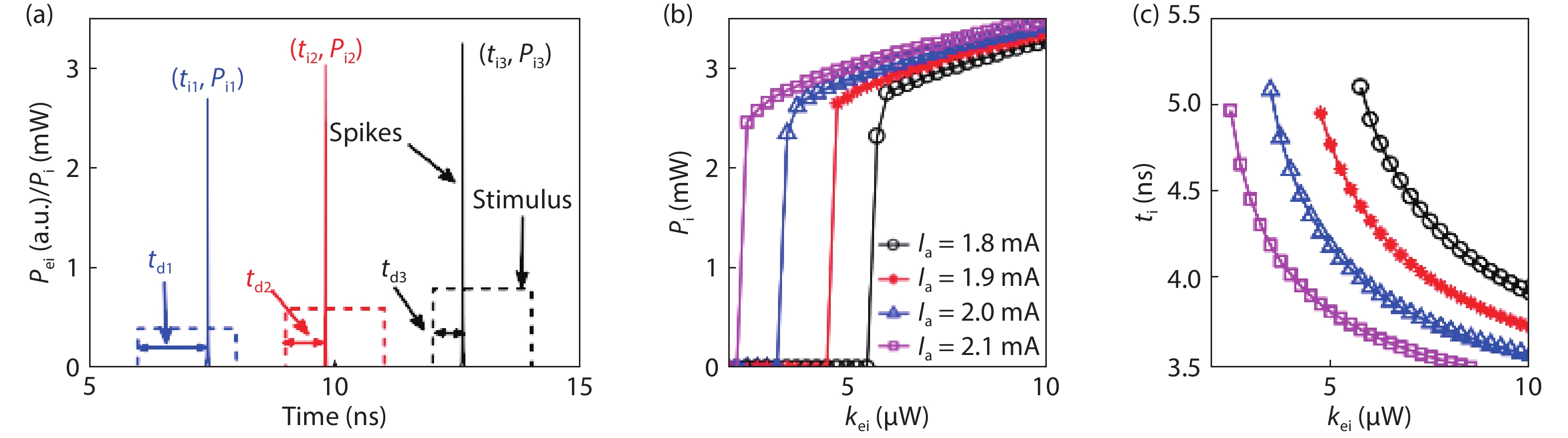
A VCSEL-SA can be employed as a photonics neuron because it possesses the excitability property behaves analogously to the LIF neuron model. The excitability properties and the spike latency of the VCSELs-SA are shown in Fig. 1[
![]()
Figure 1.(Color online) (a) Temporal output of the spike encoding based on the modeling-based photonic neuron. (b) Threshold-like response and (c) spike latency property of the modeling-based photonic neuron. © [2020] IEEE. Reprinted with permission from Ref. [
Note, the inhibitory dynamics is also important for the neural information processing. We further revealed the inhibitory dynamics based on the polarization mode competition effect in a VCSEL-SA with two coexisting polarization-resolved modes[
![]()
Figure 2.(a) Schematic diagram of inhibitory neuron based on VSCEL-SA. Reprinted from Ref.
![]()
Figure 3.(Color online) (a) Schematic diagram of all-optical exclusive OR (XOR) operator based on a single VCSEL-SA. (b) XOR output for different sets of inputs. (c) The inputs and outputs of XOR for two RZ sequences. Reprinted with permission from Ref.
2.2. Optical neuron based on VCSEL
The VCSELs have become promising candidates for artificial neuronal models due to the polarization switching or optical injection induced nonlinear dynamics. Recently, the controllable and reproducible excitation and inhibition behaviors at sub-nanosecond speeds for a commercially available VCSEL subject to the successive external stimulus have been experimentally and theoretically demonstrated[
![]()
Figure 4.(Color online) (a) The experimental setup for spiking firing and inhibition of VCSEL-based neuron. © [2018] IEEE. Reprinted with permission from Ref.
2.3. Optical neuron based on DFB
The DFB exhibits similar processing characteristics with the graded-potential-signaling-based neuron observed in the nervous system, such as temporal integration and pulse facilitation. A commercially available DFB was demonstrated to play a role in three applications of neuromorphic information processing for pattern recognition, single-wavelength STDP implementation, and sound azimuth measurement, as shown in Fig. 5[
![]()
Figure 5.(Color online) (a) The experimental setup for graded-potential-signaling-based neuromorphic processing applications with the optical neuron based on DFB, including (b, c) pattern recognition, (d, e) single-wavelength implementation of STDP, and (f, g) sound azimuth measurement[
![]()
Figure 6.(Color online) (a) The DFB-based spatiotemporal pattern recognition network with STDP learning module. The network output for patterns with (b) 3 and (c) 4 input branches, respectively. Reprinted with permission from Ref.
3. Photonic synaptic plasticity
In brains, synaptic plasticity is believed to be closely related to the learning and memory. In this section, we review the emulation of the synaptic function based on the semiconductor optical amplifier (SOA) and vertical-cavity semiconductor optical amplifier (VCSOA). The photonic STDP is focused on.
3.1. Photonic STDP based on SOA
STDP is a long-term synaptic plasticity observed experimentally in biological synapses by Bi and Poo[
![]()
Figure 7.(Color online) (a) Optical implementation of STDP. (b) The measured learning window of Optical STDP with different SOA driving current. Reprinted with permission from Ref.
3.2. Photonic STDP based on VCSOA
Note that, for the photonic STDP based on SOA, the operation current of SOA is relatively high, i.e., several tens of or hundreds of mA. When operating below threshold, the VCSEL can also be regarded as VCSOA. The photonic STDP based on the VCSOA was proposed and demonstrated experimentally and numerically[
![]()
Figure 8.(Color online) (a) Schematic diagram of photonic STDP based on VCSOA. (b) The experimental measured output pulse train corresponding to the input pulse pairs with different time interval. (c) Simulated input pulse. (d) Simulated output pulse. (e) The calculated STDP curve. Pulse 1 (Pulse 2): the optical pulse injection beam; VODL: variable optical delay line, OC: optical coupler; Circulator: optical circulator; VCSOA: vertical-cavity semiconductor optical amplifier. Bias and TEC: The bias current and temperature controller for VCSOA;
4. Photonic neural computing
In this section, we review the progress on the optical neural computing at the system level. We consider several network architectures and algorithms including photonic SNN, photonic convolutional neural network (CNN), photonic matrix computation, photonic reservoir computing (RC), and photonic reinforcement learning.
4.1. Photonic SNN
To design the algorithm for a photonic SNN, we proposed a novel framework of a fully VCSEL-based all-optical SNN and developed a self-consistent unified neuron-synapse-learning model that allows a complete learning-to-inference workflow[
![]()
Figure 9.(Color online) (a) Schematic diagram of photonic SNN based on VCSELs and VCSOAs. (b) PST as a function of the learning cycle. (c) Synaptic weights evolution during the learing process.
![]()
Figure 10.(Color online) (a) Schematic diagram of a photonic SNN based on VCSEL-SAs for the supervised spike sequence learning. (b-e) Illustration of the spike sequence learning of a typical run. © [2020] IEEE. Reprinted with permission from Ref. [
The spatiotemporal pattern classification based on supervised learning was further demonstrated based on the spatiotemporal design of the photonic SNN shown in Fig. 11(a)[
![]()
Figure 11.(Color online) (a) Architecture of the proposed all-optical SNN. (b) An example of a pattern classification task. The network is trained with (b1) a clean character image, and then, the inference was tested with a set of (b2) noisy patterns. (c) Comparison of convergence performance for supervised learning with different I of VCSOA. (d) Accuracy rate of the trained network as a function of the noise strength of the optical digital character. © [2020] IEEE. Reprinted with permission from Ref. [
In addition, sound azimuth detection was emulated in a fully connected photonic SNN consisting of VCSELs-SA[
![]()
Figure 12.(a) Schematic structure of a 2 × 2 photonic SNN architecture to detect the sound azimuth, and two PREs correspond to the right ear and left ear, respectively. (b) Responses of POST1 and POST2 when
Besides, the winner-take-all mechanism was also achieved successfully in the photonic SNN consisting of VCSELs-SA as shown in Figs. 13(a) and 13(b)[
![]()
Figure 13.(Color online) (a) Schematic diagram of WTA based on VCSELs-SA. (b) The output of VCSELM,A,B-SA for WTA mechanism. (c) Schematic diagram of pattern recognition based on the WTA machine. (d) The inputs and results of pattern recognition. (e) Schematic diagram of max-pooling operation. (f) The results of max-pooling operation. © [2020] IEEE. Reprinted with permission from Ref. [
Furthermore, associative learning and forgetting processes were emulated in a photonic SNN[
![]()
Figure 14.(Color online) (a) Schematic diagram of associative learning and forgetting processes based on VCSELs and STDP. (b) The emulation of associative learning and forgetting processes. (c) Schematic diagram of pattern recall. (d) Complete and incomplete patterns of number 8 and 5 respectively, visualization initial and final outputs of number 8 and 5 respectively. (e) The change processes of synaptic weight for number 8 and number 5. © [2020] IEEE. Reprinted with permission from Ref. [
4.2. Optical convolutional neural network
The optical implementation of CNN with fast operation speed and high energy efficiency is appealing due to its outstanding feature extraction ability[
![]()
Figure 15.(Color online) (a) The architecture of the optical convolution unit (OCU) by modulator arrays. (b) The transmission rate versus the modulation voltage of the single modulator. (c) An illustration of the serialization method. (d) The convolution results of MNIST-handwritten numbers and Fashion-MNIST data sets. Reprinted with permission from Ref.
A more complete optical CNN implementation incorporating patching scheme was demonstrated in[
![]()
Figure 16.(Color online) (a) The conceptual layout of the optical patching scheme with optical delay lines and wavelength-division-demultiplexing (WDM). (b) The experimental setup of the proposed scheme. Delayed copies of the input waveforms corresponding to (c, d) digit 2 and (e, f) 4, respectively. Reprinted with permission from Ref.
4.3. Optical matrix computation
Matrix computations form the most widely used computational tools in science and engineering, and are the basic components of neural networks for deep learning. While the electronic matrix computations suffer from limited bandwidth. Alternatively, the optical methods offer a high-speed and low-loss solution. Optical matrix computation is also essential in the optical neural computing.
The Mech-Zehnder interferometer (MZI) mesh had been demonstrated for optical matrix computation[
![]()
Figure 17.(Color online) Optical matrix computation and the application for polarization processing. (a) Special-purpose processors for optical matrix computing and polarization processing respectively. (b) Self-configuring example for the smart processors. © [2020] IEEE. Reprinted with permission from Ref. [
![]()
Figure 18.(Color online) Experimental results for photonic polarization processor chip. (a) Polarization MIMO descrambler. (b) Polarization controller. (c) Polarization analyzer. Reprinted with permission from Ref.
![]()
Figure 19.(Color online) Experimental results for self-configuring optical signal processor. (a) Multichannel optical switching. (b) Optical MIMO descramble. (c) Tunable optical filter. Reprinted with permission from Ref.
4.4. Photonic reservoir computing
RC is a brain-inspired computational paradigm originated from recurrent neural network suitable for time series processing[
An attempt at the time-delay RC systems based on VCSEL is that we proposed a four-channels RC system based on polarization dynamics in mutually coupled VCSELs[
![]()
Figure 20.(Color online) (a) System design of the Four-channels RC based on MDC-VCSELs. (b) The virtual node states matrix for each channel. (c) The NMSE values of Four-channels RC system based on MDC-VCSELs as a function of bias current for Four-channels RC and One-channel RC, respectively. Reprinted with permission from Ref.
We also have some attempts at the time-delay RC system based on semiconductor nanolaser (SNL), due to the potential of realizing photonic integrated RC system[
![]()
Figure 21.(Color online) (a) The conceptual scheme of RC based on a semiconductor nanolaser (SNL) with delayed feedback. (b) The NMSE values of SNL-based RC system as a function of the
4.5. Photonic reinforcement learning
Reinforcement learning is also a fundamental learning mechanism inspired by the brain[
The photonic reinforcement learning based on laser chaos with time-delay signature concealment was demonstrated by introducing a phase-modulated Sagnac loop in mutually delay-coupled semiconductor lasers (PMSL-MC)[
![]()
Figure 22.(Color online) (a) Experimental setup of a dual-channels chaotic system with a phase-modulated Sagnac loop. (b) Architecture for reinforcement learning based on dual-channels laser chaos. (c) The CDR as a function of cycle for the CSL-MC system and for the PMSL-MC system. (d) The convergence cycle (CC), at which the CDR reaches 0.9, as a function of coupling strength for the CSL-MC system and the PMSL-MC system. (e) The CDR as a function of the number of cycles for dual-channels and one-channel in the PMSL-MC system. (f) The CC as a function of coupling strength for dual-channels and one-channel in the PMSL-MC system. Reprinted with permission from Ref.
A further parallelized scheme for photonic decision making was experimentally demonstrated in a globally-coupled chaotic semiconductor lasers network as shown in Fig. 23[
![]()
Figure 23.(Color online) (a) The experimental setup of three globally coupled DFB lasers. (b) A parallel architecture for photonic decision making of 8-armed bandit problem. (c, d) CC and delay concealment as a function of attenuation. (e) The adaptability of the strategy to dynamically changing environment. (f) The scalability to 16-armed problem. Reprinted from Ref.
5. Conclusion and outlook
We have reviewed some representative photonic neural computing in devices, architectures, and algorithms. To further pave the way of photonics neuromorphic computing, there are still some problems that need to be addressed. The optical neuron and synapse are generally designed separately, which results in the different time scales. The optical neuron and synapse with similar time scale have to be further developed to meet up the requirements of on-line training. The design of photonic neural computing system on a chip still requires further exploration. Further attempts have to be made to reduce the area and increase the integration level.
Note, at the present stage, we think it may be more realistic to adopt an ex-situ training approach for the training process of the photonic neural network. Nevertheless, it is promising to build an integrated hardware photonic neural network for realizing the inference process. At present, the optical neuron based on spiking laser could be readily realized with III–V compound semiconductor technology such as indium phosphide (InP) and gallium arsenide (GaAs), while the weight array could be successfully implemented with silicon waveguides or resonators. It is believed that the rapid development of photonic integrated technologies will lead to a bright future for the field of photonic neural computing. For instance, a hybrid III–V and silicon photonics platform may be a candidate to realize an integrated hardware photonic neural network for inference task[
Acknowledgements
This work was supported in part by the National Outstanding Youth Science Fund Project of National Natural Science Foundation of China (62022062), by the National Natural Science Foundation of China (61974177, 61674119), by the Fundamental Research Funds for the Central Universities.
References
[1] G E Moore. Cramming more components onto integrated circuits. Electron, 38, 114(1965).
[2] M M Waldrop. The chips are down for Moore’s law. Nat News, 530, 144(2016).
[3] W Maass. Networks of spiking neurons: The third generation of neural network models. Neur Netw, 10, 1659(1997).
[4] Z F Mainen, T J Sejnowski. Reliability of spike timing in neocortical neurons. Science, 268, 1503(1995).
[5] J J Hopfield. Pattern recognition computation using action potential timing for stimulus representation. Nature, 376, 33(1995).
[6] G Q Bi, M M Poo. Synaptic modifications in cultured hippocampal neurons: Dependence on spike timing, synaptic strength, and postsynaptic cell type. J Neurosci, 18, 10464(1998).
[7] L F Abbott, S B Nelson. Synaptic plasticity: Taming the beast. Nat Neurosci, 3, 1178(2000).
[8] G Q Bi, M M Poo. Synaptic modification by correlated activity: Hebb’s postulate revisited. Annu Rev Neurosci, 24, 139(2001).
[9]
[10] K Roy, A Jaiswal, P Panda. Towards spike-based machine intelligence with neuromorphic computing. Nature, 575, 607(2019).
[11] J D Zhu, T Zhang, Y C Yang et al. A comprehensive review on emerging artificial neuromorphic devices. Appl Phys Rev, 7, 011312(2020).
[12] W Zhang, B Gao, J Tang et al. Neuro-inspired computing chips. Nat Electron, 3, 371(2020).
[13] P R Prucnal, B J Shastri, T F de Lima et al. Recent progress in semiconductor excitable lasers for photonic spike processing. Adv Opt Photon, 8, 228(2016).
[14] M A Nahmias, B J Shastri, A N Tait et al. A leaky integrate-and-fire laser neuron for ultrafast cognitive computing. IEEE J Sel Top Quantum Electron, 19, 1800212(2013).
[15] B Gholipour, P Bastock, C Craig et al. Amorphous metal-sulphide microfibers enable photonic synapses for brain-like computing. Adv Opt Mater, 5, 635(2015).
[16] Z Cheng, C Ríos, W H P Pernice et al. On-chip photonic synapse. Sci Adv, 3, e1700160(2017).
[17] J Feldmann, N C D Youngblood et al. All-optical spiking neurosynaptic networks with self-learning capabilities. Nature, 569, 208(2019).
[18] X Zhuge, J Wang, F Zhuge. Photonic synapses for ultrahigh-speed neuromorphic computing. Phys Status Solidi RRL, 13, 1900082(2019).
[19] T F de Lima, H T Peng, A N Tait et al. Machine learning with neuromorphic photonics. J Lightwave Technol, 37, 1515(2019).
[20] W W Zou, B W Ma, S F Xu et al. Towards an intelligent photonic system. Sci China Inform Sci, 63, 160401(2020).
[21]
[22] A Hurtado, I D Henning, M J Adams. Optical neuron using polarization switching in a 1550 nm-VCSEL. Opt Express, 18, 25170(2010).
[23] W Coomans, L Gelens, S Beri et al. Solitary and coupled semiconductor ring lasers as optical spiking neurons. Phys Rev E, 84, 036209(2011).
[24] A Hurtado, K Schires, I Henning et al. Investigation of vertical cavity surface emitting laser dynamics for neuromorphic photonic systems. Appl Phys Lett, 100, 103703(2012).
[25] S Y Xiang, A J Wen, W Pan. Emulation of spiking response and spiking frequency property in VCSEL-based photonic neuron. IEEE Photonics J, 8, 1504109(2016).
[26] J Robertson, T Deng, J Javaloyes. Controlled inhibition of spiking dynamics in VCSELs for neuromorphic photonics: theory and experiments. Opt Lett, 42, 1560(2017).
[27] S Y Xiang, Y H Zhang, X X Guo et al. Cascadable neuron-like spiking dynamics in coupled VCSELs subject to orthogonally polarized optical pulse injection. IEEE J Sel Top Quantum Electron, 23, 1700207(2017).
[28] T Deng, J Robertson, A Hurtado. Controlled propagation of spiking dynamics in vertical-cavity surface-emitting lasers: towards neuromorphic photonic networks. IEEE J Sel Top Quantum Electron, 23, 1800408(2017).
[29] S Y Xiang, Y H Zhang, X X Guo et al. Photonic generation of neuron-like dynamics using VCSELs subject to double polarized optical injection. J Lightwave Technol, 36, 4227(2018).
[30] T Deng, J Robertson, Z M Wu et al. Stable propagation of inhibited spiking dynamics in vertical-cavity surface-emitting lasers for neuromorphic photonic networks. IEEE Access, 6, 67951(2018).
[31] Y H Zhang, S Y Xiang, X X Guo et al. Polarization-resolved and polarization-multiplexed spike encoding properties in photonic neuron based on VCSEL-SA. Sci Rep, 8, 16095(2018).
[32] Y H Zhang, S Y Xiang, J K Gong et al. Spike encoding and storage properties in mutually coupled vertical-cavity surface-emitting lasers subject to optical pulse injection. Appl Opt, 57, 1731(2018).
[33] Y H Zhang, S Y Xiang, X X Guo et al. All-optical inhibitory dynamics in photonic neuron based on polarization mode competition in a VCSEL with an embedded saturable absorber. Opt Lett, 44, 1548(2019).
[34] S Y Xiang, n Z Ren, g Y Zhang et al. All-optical neuromorphic XOR operation with inhibitory dynamics of a single photonic spiking neuron based on VCSEL-SA. Opt Lett, 45, 1104(2020).
[35] S Y Xiang, Y H Zhang, J K Gong et al. STDP-based unsupervised spike pattern learning in a photonic spiking neural network with VCSELs and VCSOAs. IEEE J Sel Top Quantum Electron, 25, 1700109(2019).
[36] J Robertson, E Y Wade et al. Toward neuromorphic photonic networks of ultrafast spiking laser neurons. IEEE J Sel Top Quantum Electron, 26, 7700715(2020).
[37] B W Ma, W W Zou. Demonstration of a distributed feedback laser diode working as a graded-potential-signaling photonic neuron and its application to neuromorphic information processing. Sci China Inform Sci, 63, 160408(2020).
[38]
[39]
[40] R Toole, M P Fok. Photonic implementation of a neuronal algorithm applicable towards angle of arrival detection and localization. Opt Express, 23, 16133(2015).
[41] Q S Ren, Y L Zhang, R Wang et al. Optical spike-timing-dependent plasticity with weight-dependent learning window and reward modulation. Opt Express, 23, 25247(2015).
[42] R Toole, A N Tait, T F de Lima et al. Photonic implementation of spike-timing-dependent plasticity and learning algorithms of biological neural systems. J Lightwave Technol, 34, 470(2016).
[43] Q Li, Z Wang, Y S Le et al. Optical implementation of neural learning algorithms based on cross-gain modulation in a semiconductor optical amplifier. Proc SPIE, 10019, 2245976(2016).
[44] S Y Xiang, J K Gong, Y H Zhang et al. Numerical implementation of wavelength-dependent photonic spike timing dependent plasticity based on VCSOA. IEEE J Quantum Electron, 54, 8100107(2018).
[45] T Lima, B J Shastri, A N Tait et al. Progress in neuromorphic photonics. Nanophotonics, 6, 577(2017).
[46] S Song, J Kim, S M Kwon et al. Recent progress of optoelectronic and all-optical neuromorphic devices: a comprehensive review of device structures, materials, and applications. Adv Intell Syst, 2000119(2020).
[47] S Y Xiang, Y N Han, X X Guo et al. Real-time optical spike-timing dependent plasticity in a single VCSEL with dual-polarized pulsed optical injection. Sci China Inform Sci, 63, 160405(2020).
[48] Z W Song, S Y Xiang, Z X Ren et al. Spike sequence learning in a photonic spiking neural network consisting of VCSELs-SA with supervised training. IEEE J Sel Top Quantum Electron, 26, 1700209(2020).
[49] Z W Song, S Y Xiang, Z X Ren et al. Photonic spiking neural network based on excitable VCSELs-SA for sound azimuth detection. Opt Express, 28, 1561(2020).
[50] Y H Zhang, S Y Xiang, X X Guo, Wen A. et al. The winner-take-all mechanism for all-optical systems of pattern recognition and max-pooling operation. J Lightwave Technol, 38, 5071(2020).
[51] S H Wang, S Y Xiang, G Q Han et al. Photonic associative learning neural network based on VCSELs and STDP. J Lightwave Technol, 38, 4691(2020).
[52] S F Xu, J Wang, R Wang et al. High-accuracy optical convolution unit architecture for convolutional neural networks by cascaded acousto-optical modulator arrays. Opt Express, 27, 19778(2019).
[53] S F Xu, J Wang, W W Zou. Optical patching scheme for optical convolutional neural networks based on wavelength-division multiplexing and optical delay lines. Opt Lett, 45, 3689(2020).
[54] S F Xu, X T Zou, B W Ma et al. Deep-learning-powered photonic analog-to digital conversion. Light Sci Appl, 8, 66(2019).
[55] H L Zhou, Y H Zhao, G X Xu et al. Chip-scale optical matrix computation for PageRank algorithm. IEEE J Sel Top Quantum Electron, 26, 8300910(2020).
[56]
[57] H L Zhou, Y H Zhao, Y X Wei et al. All-in-one silicon photonic polarization processor. Nanophotonics, 8, 2257(2019).
[58]
[59] H L Zhou, Y H Zhao, X Wang et al. Self-configuring and reconfigurable silicon photonic signal processor. ACS Photonics, 7, 792(2020).
[60] W Maass, T Natschlager, H Markram. Real-time computing without stable states: a new framework for neural computation based on perturbations. Neur Comput, 14, 2531(2002).
[61] W Maass, T Natschlager, H Markram. Fading memory and kernel properties of generic cortical microcircuit models. J Physiol-Paris, 98, 315(2004).
[62] M Lukosevicius, H Jaeger. Reservoir computing approaches to recurrent neural network training. Comput Sci Rev, 3, 127(2009).
[63] V D S Guy, D Brunner, M C Soriano. Advances in photonic reservoir computing. Nanophotonics, 6, 561(2017).
[64] D Brunner, B Penkovsky, B A Marquez et al. Tutorial: Photonic neural networks in delay systems. J Appl Phys, 124, 152004(2018).
[65] G Tanaka, T Yamane, J B Héroux et al. Recent advances in physical reservoir computing: A review. Neur Netw, 115, 100(2019).
[66] X X Guo, S Y Xiang, Y H Zhang et al. Polarization multiplexing reservoir computing based on a VCSEL with polarized optical feedback. IEEE J Sel Top Quantum Electron, 26, 1700109(2020).
[67] X X Guo, S Y Xiang, Y H Zhang et al. Four-channels reservoir computing based on polarization dynamics in mutually coupled VCSELs system. Opt Express, 27, 23293(2019).
[68] X X Guo, S Y Xiang, Y H Zhang et al. Enhanced memory capacity of a neuromorphic reservoir computing system based on a VCSEL with double optical feedbacks. Sci China Inf Sci, 63, 160407(2020).
[69] X X Guo, S Y Xiang, Y H Zhang et al. High-speed neuromorphic reservoir computing based on a semiconductor nanolaser with optical feedback under electrical modulation. IEEE J Sel Top Quantum Electron, 26, 1500707(2020).
[70] X X Guo, S Y Xiang, Qu Y. et al. Enhanced prediction performanceof a neuromorphic reservoir computing using a semiconductor nanolaser with double phase conjugate feedbacks. J Lightwave Technol, 39, 129(2021).
[71]
[72] M Naruse, T Mihana, H Hori et al. Scalable photonic reinforcement learning by time-division multiplexing of laser chaos. Sci Rep, 8, 10890(2018).
[73] Y T Ma, S Y Xiang, X X Guo et al. Time-delay signature concealment of chaos and ultrafast decision making in mutually coupled semiconductor lasers with a phase-modulated Sagnac loop. Opt Express, 28, 1665(2020).
[74] Y N Han, S Y Xiang, Y Wang et al. Generation of multi-channel chaotic signals with time delay signature concealment and ultrafast photonic decision making based on globally-coupled semiconductor lasers network. Photonics Res, 8, 1792(2020).
[75] Z Zhou, Z Tu, B Yin et al. Development trends in silicon photonics. Chin Opt Lett, 11, 012501(2013).
[76] Z P Zhou, B Yin, J Michel. On-chip light sources for silicon photonics. Light Sci Appl, 4, e358(2015).
[77] A H Atabaki, S Moazeni, F Pavanello et al. Integrating photonics with silicon nanoelectronics for the next generation of systems on a chip. Nature, 556, 349(2018).
[78] M R Billah, M Blaicher, T Hoose et al. Hybrid integration of silicon photonics circuits and InP lasers by photonic wire bonding. Optica, 5, 876(2018).
[79] X H Guo, A He, Y K Su. Recent advances of heterogeneously integrated IIIV laser on Si. J Semicond, 40, 101304(2019).
[80] B W Bai, H W Shu, X J Wang et al. Towards silicon photonic neural networks for artificial intelligence. Sci China Inf Sci, 63, 160403(2020).
[81]
[82] Z L Ruan, Y T Zhu, P X Chen et al. Efficient hybrid integration of long-wavelength VCSELs on silicon photonic circuits. J Lightwave Technol, 38, 5100(2020).
[83] Y Y Li, Y Wang, D R Yang et al. Recent progress on optoelectronic synaptic devices. Sci Sin Inform, 50, 892(2020).
[84] G Wetzstein, A Ozcan, S Gigan et al. Inference in artificial intelligence with deep optics and photonics. Nature, 588, 39(2020).

Set citation alerts for the article
Please enter your email address
© Copyright 2018-2021 | Chinese Laser Press. All Rights Reserved 沪ICP备15018463号-20