
Y. F. Chen, C. C. Lee, C. H. Wang, M. X. Hsieh. Laser transverse modes of spherical resonators: a review [Invited][J]. Chinese Optics Letters, 2020, 18(9): 091404
- Chinese Optics Letters
- Vol. 18, Issue 9, 091404 (2020)
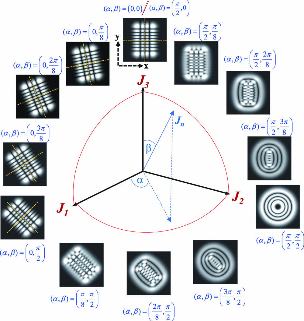
Fig. 1. Calculated patterns of HLG modes
![Calculated patterns for the standing waves given by Re[ψn1,n2(α,β)(x˜,y˜)] (golden color) as well as Im[ψn1,n2(α,β)(x˜,y˜)] (green color), corresponding to the results in Fig. 1.](/richHtml/col/2020/18/9/091404/img_002.jpg)
Fig. 2. Calculated patterns for the standing waves given by 1 .
Fig. 3. Calculated results for 30 ) and (34 ) with
Fig. 4. Calculated results for 30 ) and (34 ) with
Fig. 5. Calculated results for 30 ) and (34 ) with
Fig. 6. Calculated results for 43 ) and (45 ) with
Fig. 7. Calculated results for the standing waves of 6 .
Fig. 8. Calculated results for 43 ) and (45 ) with
Fig. 9. (a) Configuration of the single lens mode converter. Two vertical lines show the positions of the beam waists produced by the spherical matching lens and by the active axis of the cylindrical lens with focal length
Fig. 10. Experimental results (first column), numerical wave patterns (second column), and phase structures (third column) for the propagation evolution of the converted beam
Fig. 11. Experimental results (first column), numerical wave patterns (second column), and phase structures (third column) for the propagation evolution of the converted beam
Fig. 12. Experimental results (first column), numerical wave patterns (second column), and phase structures (third coulmn) for the propagation evolution of the converted beam
Fig. 13. Experimental results (first column), numerical wave patterns (second column), and phase structures (third column) for the propagation evolution of the converted beam

Set citation alerts for the article
Please enter your email address
© Copyright 2018-2021 | Chinese Laser Press. All Rights Reserved 沪ICP备15018463号-20