Guojun He, Lihua Huang, Liying Hou, Huijie Huang, "Study of beam steering based on feedback control via a pulsed laser," Chin. Opt. Lett. 13, S21401 (2015)
Copy Citation Text
We set up a pulsed beam steering system with a simple feedback control method. The system applies an integration circuit to process a 2 μs short pulsed beam with a repetition rate of 25 Hz, and employs an iteration method to correct the beam with a reasonable feedback gain factor. The beam steering system achieves a performance of 30 μm position accuracy and 30 μrad pointing accuracy, and it can not only compensate the drift of the laser source but also correct the external disturbance. The design can be directly applied as a lithography tool.
Steering of optical beams is of great interest in many industrial and scientific applications including laser surgery[1], scanning optical lithography[2], free-space laser communication[3,4], and so on. Especially, beam steering technology always plays a key role in applications such as lithography, which has stringent demands for beam pointing and position. In an actual lithography system, a beam with long-distance transmission ( in general) from the laser source to the wafer is always injected with disturbance. There are factors that degrade beam stability over the short- and long-term. In summary, these disturbance can be broadly classified into the following three types: drift of the laser source, jitter caused by environment fluctuations, and vibration of the platform[5]. The first two fluctuations are always manifested as continuous variation and have a low-frequency character; in contrast, the third is a sudden and temporal jitter.
In this work, we have designed a signal processing method aimed at handling short bursts. A simple modeling of the feedback control loop was built to give guidance for choosing a proper gain factor. Experiments were undertaken to test the performance of the controller in compensating the drift of the laser itself over a long time period and external noise which is injected by a third fast-steering mirror (FSM).
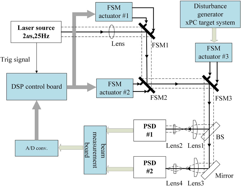
Our group has carried out some research work pertinent to beam steering and some experiments using a matrix algorithm with a continuous laser[6–8]. However, an actual lithography system tends to use a pulsed laser (such as a 193 nm ArF excimer laser) source with a short pulse width (nanosecond or microsecond level) to achieve higher peak power. On the basis of the existing experimental device, we have developed a new control design to steer the short pulsed light. The schematic of the experimental setup for beam stabilization is shown in Fig. 1. Position sensing detectors (PSDs) 1 and 2 are sensitive to position and pointing change, respectively, and FSM 1 and FSM 2 are used for correcting the pulsed light; these mirrors are the identical FSMs provided by the Fan group of the National University of Defense Technology (NUDT). FSMs have an angular range of , 3 μrad resolution, 8 μrad repeatability, and 20 μrad accuracy, and have a closed-loop bandwidth up to 250 Hz. In our work, FSM 3 is a Newport FSM-300 FSM and is used for adding disturbance to the beam.
Sign up for Chinese Optics Letters TOC. Get the latest issue of Chinese Optics Letters delivered right to you!Sign up now
In our work, a diode laser which is modulated at a repetition rate of 25 Hz and 2 μs pulse width by a signal generator is adopted. In order to detect the pulsed beam, we have designed a signal processing board (i.e., beam measurement unit board (BMUB)) to process the current signals from the PSDs. Because of such a short pulse duration, the BMUB integrated the signal instead of simply holding the signal peak value after conversion, and the integration time is no longer than the pulse width in principle. In our design, the integration time can be adjusted by the program to achieve the best performance. A simple block diagram of our BMUB design is shown in Fig. 2. Once we obtain a reliable beam position and angle deviation, we can easily use the iteration method mentioned next to compensate.
Figure 2.Block diagram of signal processing board (i.e., BMUB).
The theory of beam stabilization has been elaborated in our previous paper. Our beam stabilization method adjusts the pointing and displacement of the beam by a series of iteration compensations. The exact iteration formalism is shown in the following[9]. For simplicity, we simply consider beam alignment at one dimension. Assume is the distance between FSM 1 and FSM 2, and is the distance between FSM 2 and position decoupling plane; then we can adjust the beam to a desired position and angle by taking the following two steps which we called one iteration: first, we actuate FSM 1 to obtain zero output of PSD 1, and then actuate FSM 2 to obtain zero output of PSD 2. We define , and assume the beam has a position displacement of and an angular offset of from the desired beam state at each decoupling plane. We know that after the th iteration, the outputs at each decoupling plane are where is the beam pointing in angle decoupling plane and is the beam position in position decoupling plane. It is evident that the outputs of the system will be convergent as the iteration proceeds. The speed of convergence is closely related to the ratio of to . What we must point out is that this iteration method is completely serial and its alignment speed is not as good as that by adopting the decoupling-matrix approach, but the structure is simple for control.
In our work, a synchronizing signal of the laser triggers the BMUB to sample outputs of two PSDs to acquire the position and angle drift of the beam, which are used as feedback signals to control FSMs. We have two feedback loops to control FSM 1 and FSM 2 separately. The algorithm used for the feedback routine is given by Eqs. (2.1)–(2.3)[10], where is the observed position displacement of the beam, is an external noise of the actual system, is a feedback gain factor, and is output voltage of the controller of actuator. is the coefficient between the control voltage of FSM 1 (FSM 2) and beam position (angle) change which can be regarded as a dependent parameter, and is the time difference between two consecutive measurements. In our work where is the repetition rate of the laser, and parameter can be calibrated by manually adjusting the control voltage and observing the beam displacement
In accordance with to Eqs. (2.1)–(2.3), we can obtain the system transfer function by performing a Fourier transform of Eqs. (2.1)–(2.3) where is the transfer function of control system, is the Fourier transform of , is the Fourier transform of , and is the period of pulse.
The Nyquist stability criterion is employed to help us determine a proper gain factor which renders the system stable. Figure 3 is the Nyquist stability diagram for a gain factor varying from 0.5 to 3 by an increase of 0.5. According to the criterion, the system is stable if the Nyquist stability diagram does not contain the pole of . From Eq. (3), we can conclude that when the gain factor is in range of 0–2, the system will be stable; furthermore, the overall stability does not depend on the frequency.
Figure 3.Nyquist stability diagram for different gain factors.
Figure 4 shows the step response of the system with , and we show only outputs of two PSDs in the vertical axis for simplicity. In our work, the exact time interval of adjacent samples is 40 ms which equals the period of the laser source. Obviously, we only perform one adjustment to make the beam point within 30 μrad and the beam position within 30 μm; that is to say, it is possible for us to make the correction pulse to pulse. The two steps in each iteration can be simplified into one adjustment and we can adjust the gain factor to achieve the best performance by observing the step response of the system.
Figure 4.Step response using our iteration method: (a) vertical pointing error; (b) vertical position error.
In Fig. 5, we demonstrate the PSD output under an external noise which is shown in the red rectangle. An NI PCI-e 6263 card is used to drive a Newport FSM-300 (FSM 3), and a LabVIEW program is built to add disturbance to system which occurs at unpredictable times with random amplitude. The results show that the feedback control mechanism is effective for quickly correcting disturbances which occur in bursts. The pointing error is always corrected within our tolerance (as the blue lines show) faster than that of the position error. In most cases, the correcting time of the position error is 2 or 3 times longer than that of the pointing error. One reason is that in our iteration, we use two feedback closed loops to control FSM 1 and FSM 2 with the same gain factor which may not be optimal for the two loops. Another reason is the detecting error which is caused by our BMUB and the error of the analog to digital convertor.
Figure 5.Error for external disturbance suppression: (a) vertical pointing error; (b) vertical position error.
The system performance with the feedback control off and on is shown in Figs. 6 and 7, respectively. Our plot data comes from 3 h sampling with a 20 s sample interval, from which we can see the system has a position error of 0.05 mm and a pointing error of 0.35 mrad on average. The pointing error drifts from the initial 0.35 to 0.375 mrad slowly in 3 h. Obviously, the beam is corrected to the zero position and pointing by our steering system, and the maximum swing of the pointing error is reduced from 46 to 35 μrad. Nevertheless, the pointing error exceeds our tolerance (as the blue lines show); 30 μrad, 8%, which is caused by the detecting error to some extent, and this is what we should improve in future work. Another possible reason is the accuracy of the FSMs is a little low.
Figure 6.Error without control: (a) vertical pointing error; (b) vertical position error.
In conclusion, the current pulsed beam steering system with a simple feedback method achieves a performance of 30 μm position accuracy falling within a tolerance of 100%, and 30 μrad pointing accuracy falling within a tolerance of 92%, and it can not only compensate the drift of the laser source but also correct the external disturbance. The design can be directly applied as a lithography tool.
References
[1] N. O. Perez-Arancibia, J. S. Gibson, T.-C. Tsao. IEEE Trans. Control Syst. Technol., 20, 31(2012).
[2] Z. Qingkun, P. Ben-Tzvi, F. Dapeng, A. A. Goldenberg. 2008 International Workshop on Robotic and Sensors Environments, 144(2008).
[3] X. Wei, L. Yanbing, L. Shuang. 2010 2nd International Conference on Information Engineering and Computer Science (ICIECS), 4(2010).
Guojun He, Lihua Huang, Liying Hou, Huijie Huang, "Study of beam steering based on feedback control via a pulsed laser," Chin. Opt. Lett. 13, S21401 (2015)