Zhuo Wang1,†, Yao Liang2,3,5,†,*, Jiaqi Qu4..., Mu Ku Chen2,3, Mingjie Cui4, Zhi Cheng4, Jingcheng Zhang2,3, Jin Yao2,3, Shufan Chen2,3, Din Ping Tsai2,3,6,* and Changyuan Yu4,7,*|Show fewer author(s)
1Photonics Research Institute, Department of Electrical Engineering, The Hong Kong Polytechnic University, Kowloon, Hong Kong, China
2Department of Electrical Engineering, Centre for Biosystems, Neuroscience, and Nanotechnology, City University of Hong Kong, Kowloon, Hong Kong, China
3State Key Laboratory of Terahertz and Millimeter Waves, City University of Hong Kong, Kowloon, Hong Kong, China
4Photonics Research Institute, Department of Electronic and Information Engineering, The Hong Kong Polytechnic University, Kowloon, Hong Kong, China
Zhuo Wang, Yao Liang, Jiaqi Qu, Mu Ku Chen, Mingjie Cui, Zhi Cheng, Jingcheng Zhang, Jin Yao, Shufan Chen, Din Ping Tsai, Changyuan Yu, "Plasmonic bound states in the continuum for unpolarized weak spatially coherent light," Photonics Res. 11, 260 (2023)
Copy Citation Text
Plasmonic resonances empowered by bound states in the continuum (BICs) offer unprecedented opportunities to tailor light–matter interaction. However, excitation of high quality-factor (-factor) quasi-BICs is often limited to collimated light at specific polarization and incident directions, rendering challenges for unpolarized focused light. The major hurdle is the lack of robustness against weak spatial coherence and poor polarization of incident light. Here, addressing this limitation, we demonstrate sharp resonances in symmetric plasmonic metasurfaces by exploiting BICs in the parameter space, offering ultraweak angular dispersion effect and polarization-independent performance. Specifically, a high- () resonance with near-perfect absorption () is obtained for the input of unpolarized focused light covering wide incident angles (from 0° to 30°). Also, giant electric and magnetic field enhancement simultaneously occurs in quasi-BICs. These results provide a way to achieve efficient near-field enhancement using focused light produced by high numerical aperture objectives.
1. INTRODUCTION
Plasmonic resonances can realize strong electromagnetic field enhancement in subwavelength dimensions. This feature attracts extensive interest in fields that require strong light–matter interactions, such as lasing [1], optical modulation [2], nonlinear optics [3], and ultrasensitive sensing [4]. The coefficient of field enhancement of an optical antenna at the resonant wavelength can be described as [5] where is the electric field in the region of energy concentration, is the incident electric field, and is the effective mode volume. The total quality-factor (-factor) consists of the radiation -factor () and the dissipation -factor (), . Therefore, a basic method for improving the optical field enhancement is to increase the total -factor in the condition of critical coupling () [6,7]. To boost -factors, the radiation losses and dissipation losses of resonant modes need to be reduced. For more than a decade, the concept of bound states in the continuum (BICs) has been developing in the fields of optics [8–10], which suggests effective ways to achieve high- resonances. The BICs are nonradiative states embedded in the spectra of the radiation continuum. In ideal media without dissipation losses, the -factors of BICs approach infinity because of the total elimination of radiation losses. When the conditions of BICs are slightly tuned by breaking the in-plane symmetry [11] or destroying the condition of interfering resonances [12], BICs evolve into quasi-BICs with finitely high -factors. Up to now, the phenomena of high- quasi-BICs have been studied in the photonic [13–16], plasmonic [17–20], and hybrid plasmonic-photonic systems [12,21]. Compared with photonic modes in dielectric materials, plasmonic modes of metals allow smaller scales of light localization to produce stronger optical field enhancement [22]. Exploiting BICs in plasmonic metasurfaces can create high- resonances with small mode volume, which, according to Eq. (1), can further boost the light field intensity [17].
Apart from -factor engineering, another method to increase light enhancement is to use condensers to focus light into a small spot. However, high- plasmonic resonances and focused light beams generated by high numerical aperture (NA) objectives often repel each other. This is related to a fundamental incompatibility between them. Specifically, excitation of high- plasmonic resonances, surface lattices resonances (SLRs), for example, often requires collimated light with strong spatial coherence due to ultrastrong angular dispersion effects [23,24]. However, the focused light has poor spatial coherence (proportional to ) [25]. In particular, plasmonic quasi-BICs are often angular dispersive [26,27]. Thus, current studies face challenges in the excitation of high- resonances using focused light beams.
Recently, some pioneering works showed insights into the incompatibility challenges. For example, tailoring near-field coupling of plasmonic meta-atoms within a deep subwavelength scale can realize ultraweak angular dispersion, but the -factors of resonances are often very low () [28]. Also, although plasmonic bionic structures can support SLRs with high- quasi-BICs and flat band operation (almost no angular dispersion), their anisotropic nature renders them strongly polarization-selective [29]. Besides, recent investigations on high-index isotropic nanostructures on a low-index spacer and a ground metal film show high- resonances empowered by BICs [30,31]. For the quasi-BICs found in parameter space, low polarization dependence was demonstrated by collimated light at normal incidence in experiments [30]. Utilizing the interaction between magnetic dipole (MD) resonances and surface plasmon polaritons, high- resonances engineered by the Friedrich–Wintgen (FW) BIC [32] were achieved in large incident angles [31]. However, the angular dispersion inconsistency between transverse magnetic (TM) waves and transverse electric (TE) waves makes it difficult to excite high- quasi-BICs by unpolarized focused light. Nevertheless, to the best of our knowledge, there is no report on strong electromagnetic field enhancement based on a metasurface simultaneously having the properties of ultraweak angular dispersion, polarization insensitivity, and high -factor.
Sign up for Photonics Research TOC. Get the latest issue of Photonics Research delivered right to you!Sign up now
In this work, we alleviate the restriction of spatial coherence on the generation of high- resonances by designing a plasmonic metasurface having a deep subwavelength period. Arrays of metal–insulator–metal nano blocks on a dielectric spacer are employed to generate resonant modes that are insensitive to wave-vector direction and polarization of incident light. By tuning the thickness of the spacer, quasi-BICs with perfect absorption (PA) can be generated in the near-infrared wavelength band to greatly enhance the electromagnetic field intensity. The engineered quasi-BICs are demonstrated in simulation to have the characteristics of ultraweak angular dispersion, polarization insensitivity, and high -factor. Importantly, the designed plasmonic metasurface is predicted to generate resonances with absorption amplitude greater than 90% and -factors up to 71 under the illumination of unpolarized light focused by an objective with an NA of 0.5 (elevation angle covers 0° to 30°). Our results open a new route to substantial electromagnetic field enhancement using unpolarized light with weak spatial coherence.
2. RESULTS AND DISCUSSION
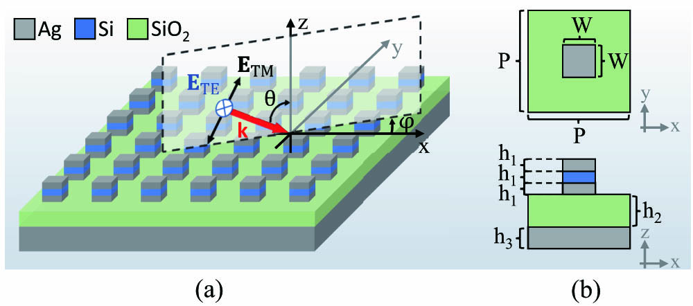
The schematic of the designed plasmonic metasurface is shown in Fig. 1. Arrays of nanoblocks are placed on a silica () spacer. The periods along the and directions are the same. Two silver (Ag) layers and a silicon (Si) layer are stacked in the normal direction to construct the nanoblock; each of the layers has the same thickness and side length . An Ag layer is added at the bottom of the spacer to prevent the transmission of light. Under the excitation of electromagnetic fields, the free charges in the two Ag layers and the bound charges in the middle Si layer of the nanoblock can form closed-loop currents, hence, generating strong magnetic-dipole responses with the dipole moment parallel to the plane [33]. The parameters are , , , and . In addition, the thickness of the spacer is denoted by . Through tuning , the BIC supported by the metasurface can be found. For an incident plane wave, represents the elevation angle of the wave vector with respect to the axis, and denotes the azimuth angle between the incident plane and the axis.
Figure 1.Schematic of the plasmonic metasurface. (a) The plasmonic metasurface consists of periodic arrays of Ag–Si–Ag nanoblocks, a spacer, and a bottom Ag layer. In the incident plane, represents the elevation angle of incidence between the wave vector and the axis. The azimuth angle between the incident plane and the axis is denoted by . (b) Top and front views of a unit cell of the metasurface.
Our simulations are carried out by using the commercial software COMSOL Multiphysics (see Appendix A). We consider an -polarized plane wave incident on the metasurface from the normal direction. The upper half of Fig. 2(a) shows the simulated reflection spectra and -factors of eigenmodes (red dots) under different spacer thicknesses (). For comparison, the eigenmode spectra (blue dots) are displayed in the lower half of Fig. 2(a). The wavelengths of eigenmodes fit well with the central resonant wavelengths of the reflection spectra. The error bars in the lower half of Fig. 2(a) describe the full width at half maximum (FWHM) of the reflection spectra. It can be found that when approaches 150 nm, the linewidth of reflection spectra decreases constantly until it becomes zero at ; meanwhile, the resonant dip of reflection spectra also disappears. In addition, the -factor of the eigenmode reaches the maximum value of 126 when . These results indicate that the resonant mode hidden here does not couple with the far-field radiation; the radiation loss is eliminated. This typical phenomenon points to the existence of BIC. When the state shifts from the BIC to quasi-BICs, the resonant depth first increases and then decreases. Two states of PA that have almost zero reflection can be found in Fig. 2(a). The first (PA1) and second (PA2) states of PA exist at and 210 nm, respectively, of which the radiation loss is balanced with the dissipation loss to satisfy the condition of critical coupling (). The evolution of far-field radiation patterns of a unit cell from quasi-BICs to the BIC is shown in Fig. 2(b). A BIC occurs at , where the direction radiation vanishes, indicating no radiation loss. At points that deviate from the BIC position (quasi-BICs), the direction radiation gradually increases. Remarkable enhancement of electromagnetic fields happens at the two PAs. Figures 2(c) and 2(d) illustrate the enhancement of electric and magnetic fields, respectively. The field enhancement coefficient is expressed by the ratio of the maximum electric or magnetic field intensity of the resonant mode to those of the incident plane wave ( or ). It can be found that, and reach the peaks when the reflection falls to the valleys. PA2 has a higher -factor () than PA1 (); consequently, the field enhancement at PA2 is slightly higher than that at PA1. The largest enhancement coefficients of the electric and magnetic fields at PA2 are 1435 and 2580, respectively. Electric and magnetic field distributions of PA2 at the wavelength of 1428 nm are shown in Figs. 2(e) and 2(f), respectively. The electromagnetic field mainly concentrates in the Si region. According to the polarization direction of the electric field, the displacement currents and conduction currents form closed-loop currents in the plane inside the nanoblock. The corresponding magnetic field distribution shows a pattern like an MD. Using the formulas of multipole decomposition [34,35] (see Appendix B) we obtained that the MD has the maximum radiation power at the resonant wavelength for PA1. For PA2, the resonance is dominated by both the MD and the toroidal dipole (TD). Therefore, the stronger magnetic field enhancement compared with the electric field enhancement can be attributed to the domination of the MD. Using the concept of energy density [36], we estimated the effective mode volume () with the reference to the strongest point of the electric field (see Appendix C). The calculated results at PA1 and PA2 are and , respectively, which shows a good ability of mode confinement on the deep subwavelength scale.
Figure 2.Simulation results of normal incidence. (a) Reflection spectra and eigenmode -factors (red dots) of the plasmonic metasurface versus the spacer thickness in the case of normal incidence by an -polarized plane wave (upper half). Eigenmode spectra and the FWHM extracted from the reflection spectra are shown by blue dots and error bars, respectively (lower half). (b) The far-field radiation patterns of a unit cell show the evolution from quasi-BICs to the BIC when changing . (c), (d) Electric and magnetic field enhancement of the two PAs (PA1 at , PA2 at ), respectively. (e), (f) Electric and magnetic field distributions of PA2, respectively, when the wavelength is 1428 nm.
Capturing light covering a wide range of incident angles is of significance to further improve electromagnetic field enhancement. First, schematically illustrated in Fig. 3(a), consider a relatively simple case of oblique incidence where only is changed while is identically equal to zero. The results of PA1 () are shown in Fig. 3(b). It can be found that the resonance has ultraweak angular dispersion with respect to whether it is excited by TM waves or TE waves. With the increase of , the reflection and resonant linewidth increase gradually. The white dashed contour indicates the reflection of 0.1. It is shown that the maximum with reflection less than 0.1 is 38° and 28° for TM and TE illuminations, respectively. However, the -factor decreases quickly with the growth of , which is not conducive to the production of sharp resonances. For PA2 (), the results are shown in Fig. 3(c). The reflection spectra of PA2 also have very weak angular dispersion with respect to . An interesting phenomenon can be found that accidental BICs [37] exist when is around 50°. For both TM and TE plane waves, thanks to accidental BICs, -factors increase constantly from 63 to over 90 when grows from 0° to 30°. Therefore, high -factors can be maintained at oblique incidence, which is the main advantage over PA1. However, the preservation of large -factors is at the cost of the range of under near-perfect absorption. In this case, for both TM and TE plane waves, the range of for the reflection smaller than 0.1 narrows to [0°, 26°].
Figure 3.Simulation results of oblique incidence. (a) Schematic of obliquely incident plane waves in the case of zero azimuth angle (); (b), (c) the reflection spectra and -factors versus the elevation angle () of incidence under the illumination of TM and TE plane waves in the incident plane when and , respectively. The white dashed curves represent contours with a reflection of 0.1. (d) Schematic representation of an -polarized plane wave propagating through an objective onto the metasurface; (e), (f) the reflection against different and of incidence in the cases of at the wavelength of 1390 nm and at the wavelength of 1428 nm, respectively, where the yellow contours represent a reflection of 0.1. Polarization distributions in different incident planes of the focused light corresponding to (d) are illustrated in (g), (h), and (i).
Then, the variations of and are considered simultaneously to mimic the real situation that the incident light is focused by an objective. As illustrated by Fig. 3(d), when a linearly polarized plane wave is focused by an objective, the polarization direction of the transmitted light varies in different incident planes with respect to the metasurface. Detailed discussions on the change of polarization direction of linearly polarized beams after they are deflected through a lens can be found in Refs. [38,39]. For instance, if the incident plane wave is polarized in the direction, the focused light is purely TM-polarized in the incident plane, as shown in Fig. 3(g). On the contrary, in the incident plane, there is only the TE-polarized component, as indicated by Fig. 3(h). In the rest of the incident planes, the polarization state is a mixture of TM and TE, as illustrated in Fig. 3(i). Therefore, it is necessary to understand the polarization response of the metasurface when the excitation light is in different incident planes. Because of the symmetry and in-plane mirror symmetry of the metasurface, only needs to vary from 0° to 45° to represent all possible scenarios. For PA1, the incident wavelength is selected as 1390 nm, which is the resonant wavelength of the normal incidence; the results are shown in Fig. 3(e). In the same way, the incident wavelength is chosen at 1428 nm for PA2 as shown in Fig. 3(f). The results reveal that has very weak influence on the resonance. According to the yellow contours, it can be found that both PA1 and PA2 can achieve absorption amplitude exceeding 90% at any . TM and TE polarization states have slightly different responses to the change of . When increases from 0° to 45°, the contour of 0.1 moves toward a larger for the TE incident light, whereas the TM incident light has the opposite trend. Compared with PA2, at any , PA1 has a larger range of for achieving reflection less than 0.1. However, PA2 has higher Q-factors, which is more conducive to field enhancement with narrow linewidth.
The average reflection spectra () of the metasurface under the multiple-angle incidence of both TM and TE plane waves are calculated by where and are the reflection spectra excited by TM and TE plane waves, respectively, at the particular angle (, ) of incidence. and represent the number of samples of and , respectively. Comparing the reflection spectra of in Fig. 8 of Appendix D and the results in Figs. 3(b) and 3(c), we can see that even a maximum change in has little influence on the reflection spectra. Therefore, it is reasonable to approximate the average reflection spectra of the focused light through an objective by only considering the average results of and 45°. The elevation angle changes from 0° to 30° in steps of 2°, as illustrated in Fig. 4(a). The results are shown in Fig. 4(b). For the metasurface with , the reflection dip exists at with an FWHM of . According to the formula , the calculated -factor is 53. When changes to 210 nm, the central resonant wavelength shifts to 1425 nm, and the FWHM narrows to 20 nm. Hence, the -factor increases to 71. This result further demonstrates that the metasurface has a better electromagnetic field enhancement at the condition of PA2. It can be concluded that the metasurface can achieve near-perfect absorption (reflection dip less than 0.1) with the -factor up to 71 when illuminated by focused light generated through an objective with (the maximum is 30°). The effects of fabrication deviations are investigated in Appendix E. Under the influences of rounded-corner deformation and pyramid-like deformation, the properties of ultraweak angular dispersion, polarization insensitivity, and high -factor are maintained well for the metasurface. However, the resonant dip has a relatively large shift with the deformations. Therefore, we need to limit the inhomogeneity of unit cells in actual samples to avoid the decrease in -factors.
Figure 4.Average reflection of plasmonic metasurfaces. (a) Schematic of multiangle incidence. The incident light contains TM and TE plane waves with equal intensity. Two azimuth angles of (blue region) and 45° (red region) are considered. The elevation angle varies from 0° to 30° in steps of 2°. (b) The average reflection spectra in the cases of and .
To clarify the characteristics of ultraweak angular dispersion, polarization insensitivity, and high -factor, we take the case of as an example to calculate the band structures and -factors under different () of periodic boundary conditions, where and are unit vectors in the and directions, respectively. The results are shown in Fig. 5. In the reciprocal lattice space, and represent the wavenumbers of the eigenmodes in the and directions, respectively. Two types of eigenmodes can be found in the studied wavelength band. The polarization direction of the magnetic field in mode 1 (M1) is mainly perpendicular to , while that in mode 2 (M2) is mainly parallel to . Figure 5(a) illustrates the magnetic field profiles of M1 and M2 in the middle cross section of the nanoblock in the conditions of and (0.18, 0.18). It can be found that the magnetic field profile rotates with the change of the direction of . Band structures of M1 and M2 are shown in Figs. 5(b) and 5(c), respectively. The resonant wavelength () decreases slowly with the increase of . In the range circled by the black contours, the offset of relative to 1428 nm is less than 5 nm. Moreover, in this range, the of M1 and M2 are almost the same. Such strong mode degeneracy gives rise to polarization insensitivity. In the presence of external incident light, the incidence of TM waves mainly excites the M1, and TE waves mainly excite the M2. Because of the requirement of wave-vector matching, the equivalent and of incidence can be obtained by and , respectively, where . It can be obtained from Figs. 5(b) and 5(c) that almost does not change with . In the meantime, the decrease in with is limited. The distributions of the equivalent corresponding to the in Figs. 5(b) and 5(c) are shown in Figs. 5(d) and 5(e), respectively. Taking the contours of and as references, it shows that when increases from 0° to 28°, the only decreases by about 5 nm. Therefore, the average angular dispersion is around when . Such a weak angular dispersion makes it possible to capture convergent light with low spatial coherence. The -factors illustrated in Figs. 5(f) and 5(g) were calculated using the resonant angular frequency and the decay time of oscillation according to the definition . Again, we can see that has a negligible influence on -factors. When increases from 0 to , the -factor first increases and then decreases. It reaches the maximum value of about 130 in the vicinity of , where the corresponding is around 50°. Compared with the results in Fig. 3(c), the regions with the highest -factor in Figs. 5(f) and 5(g) correspond to the location of accidental BICs. Finally, benefiting from the properties of ultraweak angular dispersion () and polarization insensitivity, the designed plasmonic metasurface can achieve an absorption amplitude higher than 90% for the focused light coming from a high-NA () with -factors up to 71.
Figure 5.Band structures and -factors of the plasmonic metasurface when . M1 and M2 represent the eigenmodes in which the polarization direction of the magnetic field is mainly perpendicular and parallel to the reciprocal lattice vector , respectively. (a) Magnetic field profiles of M1 and M2. (b), (c) Eigenwavelengths of M1 and M2, respectively, the black contours represent . (d), (e) Equivalent elevation angles of M1 and M2, respectively, the yellow dashed contours represent . (f), (g) -factors of M1 and M2, respectively.
In summary, to the best of our knowledge, we first proposed a symmetric plasmonic metasurface that can simultaneously achieve ultraweak angular dispersion, polarization insensitivity, and high- resonances. By adjusting the thickness of the spacer, BICs can evolve into quasi-BICs to form strong resonances without breaking the in-plane symmetry. Thus, high- quasi-BICs with PA can be excited in the condition of normal incidence. In addition, accidental BICs prevent the fall of -factors when the elevation angle of incidence () increases. Consequently, high -factors were maintained larger than 63 when varies from 0° to 30°. The deep subwavelength unit cell of the metasurface can support resonances dominated by MD and TD, which have ultraweak influences by polarization and wave-vector direction of the incident light. Therefore, the azimuth angle of incidence () has negligible effects on the resonant wavelength, absorption amplitude, and -factor. Moreover, the average angular dispersion with respect to is very weak, with a value of in the range from 0° to 28°. Based on simulation results, the metasurface can generate high- () resonances of near-perfect absorption () when illuminated by focused light produced by a high-NA () objective. Our results provide a new way to produce significant electromagnetic field enhancement using unpolarized weak spatially coherent light. It will promote the development of fields that require strong light–matter interactions, such as lasing, optical modulation, nonlinear optics, and ultrasensitive sensing.
APPENDIX A: NUMERICAL METHOD
We calculated the reflection spectra, the electromagnetic field enhancement, and the eigenmodes of the designed plasmonic metasurface by COMSOL Multiphysics. As shown in Fig. 6, at the transverse boundaries of a unit cell, Floquet periodic boundary conditions were applied in the and directions. At the top and bottom boundaries of the physical domain, two perfectly matched layers (PMLs) were employed to eliminate the reflection from the boundaries. For the simulation of reflection spectra, a top port was used for plane wave input. The Floquet -vector () was equal to the transverse wave vector of the incident plane wave. Physics-controlled mesh with an extremely fine size was used, and free tetrahedral mesh and swept mesh were applied to the physical domain and the PML domain, respectively. The maximum mesh sizes of the nanoblock and the spacer were refined to 45 and 50 nm, respectively, for accurate calculation. For the simulation of eigenmodes, the port on the top boundary of the model was disabled to eliminate the input excitation. Then, the wave vectors for Floquet periodicity along the and directions on the transverse boundaries were set as and , respectively. The values of and were chosen from 0 to 0.54, covering the variation of from 0° to 75°. The refractive indices of and Si were chosen according to the Sellmeier formula [40] and data obtained by Li [41], respectively. Material losses of and Si were neglected. The optical property of Ag was modeled by the experimental results obtained by Johnson and Christy [42].
Figure 6.Simulation settings. Floquet periodic boundary conditions were applied in the and directions. Two PMLs were added in the direction at the top and bottom of the physical domain.
To illustrate the composition of the excited resonant modes, the moments of electric dipole (ED), MD, TD, electric quadrupole (EQ), and magnetic quadrupole (MQ) were calculated [34,35], where is the total volume current density, is the position vector, is the optical angular frequency, is the light speed in vacuum, and the subscripts and represent the Cartesian coordinate components , , and . The radiated power of the multipoles can be represented by the induced currents [34],
Figure 7 shows the calculated radiated power spectra of the plasmonic metasurfaces in the case of normal incidence by an -polarized plane wave. In the case of , the resonance mainly consists of an ED, an MD, and a TD. However, when increases to 210 nm, the ED falls to the minimum, and only the MD and the TD are left to dominate.
Figure 7.Multipole decomposition of the plasmonic metasurface. The radiated power versus wavelength contributed by ED, MD, TD, EQ, and MQ when an -polarized plane wave illuminates on the metasurface from the normal direction. (a) ; (b) .
The electromagnetic energy density stored in lossy materials can be expressed as [36] where is the relaxation time in the Drude free-electron theory (for Ag is [42]); and are the real and imaginary parts of the dielectric function, respectively. Selecting the point of the maximum electromagnetic field enhancement as the reference, the effective mode volume can be defined as where represents the position of the maximum electromagnetic field enhancement.
APPENDIX D: REFLECTION SPECTRA WHEN THE AZIMUTH ANGLE IS 45°
When the azimuth angle is kept at 45°, the reflection spectra are described in Fig. 8 as functions of the elevation angle . The white dashed contour shows the wavelength ranges of reflection less than 0.1. We can see that with the change of , the contour only has a slight deflection. It suggests that the ultraweak angular dispersion regarding is well maintained when . In the case of , TM and TE incident light can obtain reflection values smaller than 0.1 when and , respectively. In addition, when , the range of for achieving reflection less than 0.1 is from 0° to 26°. Compared with the results of in Figs. 3(b) and 3(c), it can be concluded that the increase of from 0° to 45° has little effect on the reflection spectra.
APPENDIX E: INFLUENCE OF FABRICATION DEVIATIONS
The designed metasurface can be fabricated using mature nanofabrication methods such as electron beam lithography (EBL). However, the inevitable manufacturing errors will degrade the performance of the actual sample. Here, when , we consider two typical deformations in nanoblock fabrications [43], as illustrated in Fig. 9(a). One is a deformation of corners into rounded corners, and the other one is a pyramid-like deformation. For the first kind of deformation, the radius of rounded corners is set as , which is reasonable, since EBL machining accuracy can be controlled within 10 nm [44]. The simulated average reflection spectrum obtained by Eq. (2) is shown in Fig. 9(b). It can be seen that the high -factor is maintained in this case; however, the central resonant wavelength decreases by 11 nm to 1414 nm compared with the result in Fig. 4(b). For the second kind of deformation, the ratio of the top edge to the bottom edge is chosen as . This assumption is reasonable according to the fabrication result in the Supplementary Materials of Ref. [43]. The result in Fig. 9(c) shows that such pyramid-like deformation decreases the -factor to 64; also, the resonant wavelength has a larger blueshift to 1408 nm. Comparing the results of the two deformations, the pyramid-like one has heavier influence on the average reflection spectrum. Although the properties of ultraweak angular dispersion, polarization insensitivity, and high -factor are kept well for the metasurface when the deformations are introduced, the resonant wavelength shift caused by the inhomogeneity of the unit cells will reduce the -factor of fabricated samples.
Figure 8.Reflection spectra of oblique incidence when in the cases of (a) and (b) . The white dashed curves represent contours with a reflection of 0.1.
Figure 9.Influence of fabrication deviations when . (a) Schematic of deviations. The first case is that corners are deformed into rounded corners, where represents the radius of rounded corners. The second case is a pyramid-like deformation, where the side length of the top surface is smaller than that of the bottom surface . (b) Average reflection spectra in the case of rounded corners; (c) average reflection spectra in the case of pyramid-like deformation.
Zhuo Wang, Yao Liang, Jiaqi Qu, Mu Ku Chen, Mingjie Cui, Zhi Cheng, Jingcheng Zhang, Jin Yao, Shufan Chen, Din Ping Tsai, Changyuan Yu, "Plasmonic bound states in the continuum for unpolarized weak spatially coherent light," Photonics Res. 11, 260 (2023)