• Laser & Optoelectronics Progress
  • Vol. 56, Issue 19, 190801 (2019)
Hongxing He*
Author Affiliations
  • Kunming Institute of Physics, Kunming, Yunnan 650223 China
  • show less
    DOI: 10.3788/LOP56.190801 Cite this Article Set citation alerts
    Hongxing He. Medium Wave Infrared Optical System Based on Three Group Linkage Continuous Zoom[J]. Laser & Optoelectronics Progress, 2019, 56(19): 190801 Copy Citation Text show less
    Principle of three group linkage continuouszoom MWIR optical system
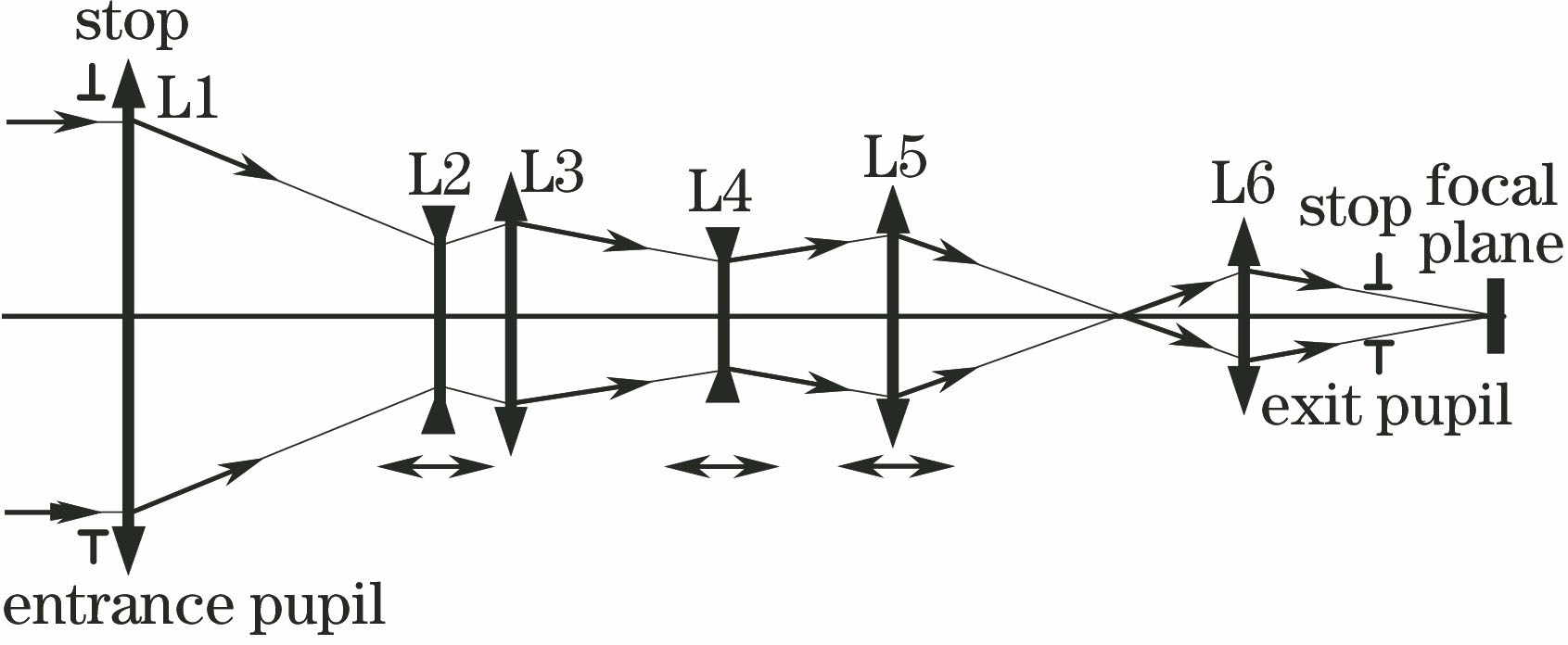
    Fig. 1. Principle of three group linkage continuouszoom MWIR optical system
    Zoom and compensation diagram of three group linkage continuous zoom MWIR optical system
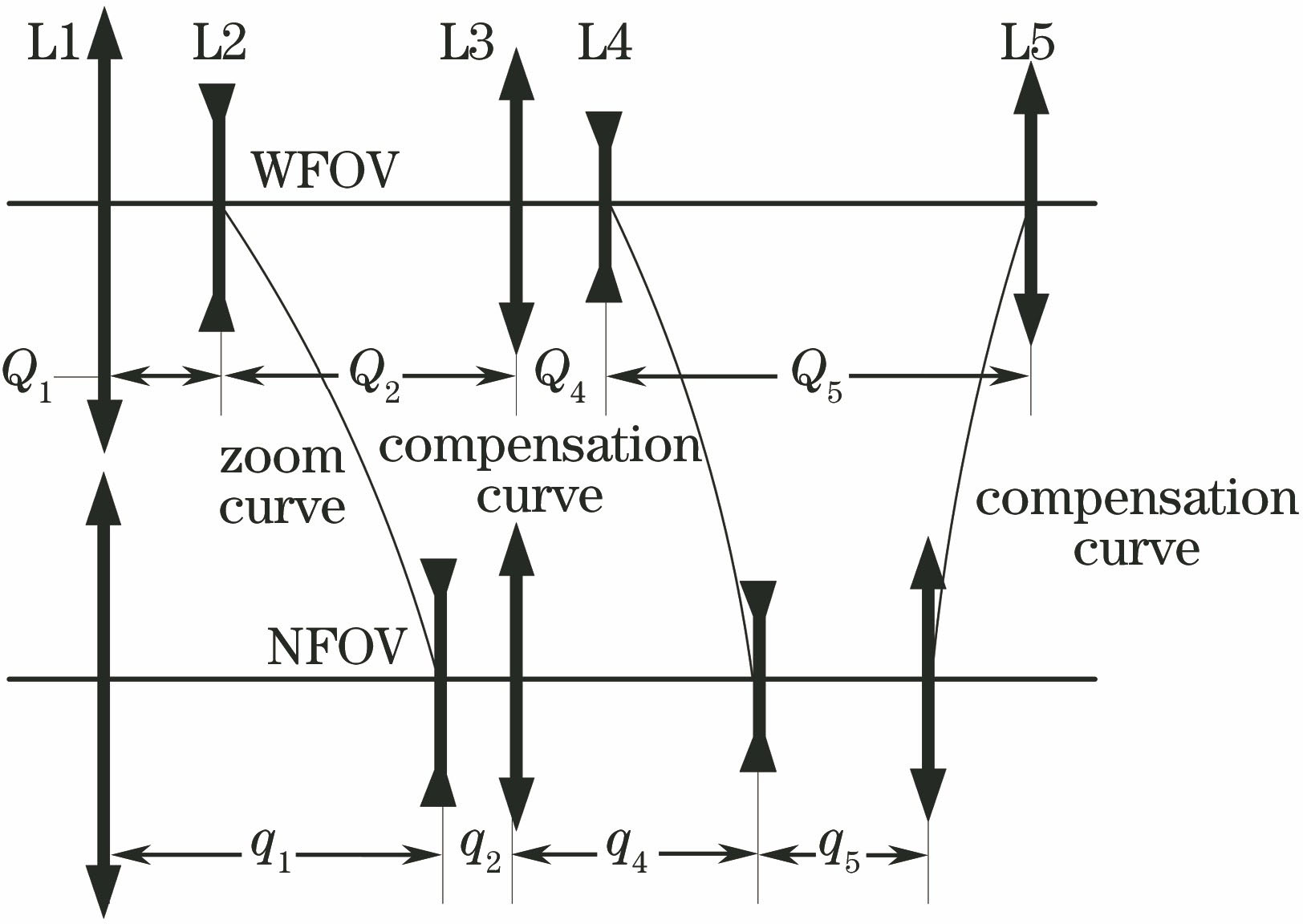
    Fig. 2. Zoom and compensation diagram of three group linkage continuous zoom MWIR optical system
    Diagram of three group linkage continuous zoom MWIR optical system
    Fig. 3. Diagram of three group linkage continuous zoom MWIR optical system
    Three-dimensional fold plot of three group linkage continuous zoom MWIR optical system. (a) Front view; (b) slide view
    Fig. 4. Three-dimensional fold plot of three group linkage continuous zoom MWIR optical system. (a) Front view; (b) slide view
    Spot diagrams of the optical system. (a) NFOV; (b) the first MFOV; (c) the second MFOV; (d) the third MFOV; (e) the fourth MFOV; (f) WFOV
    Fig. 5. Spot diagrams of the optical system. (a) NFOV; (b) the first MFOV; (c) the second MFOV; (d) the third MFOV; (e) the fourth MFOV; (f) WFOV
    MTF curves of the optical system. (a) NFOV; (b) the first MFOV; (c) the second MFOV; (d) the third MFOV; (e) the fourth MFOV; (f) WFOV
    Fig. 6. MTF curves of the optical system. (a) NFOV; (b) the first MFOV; (c) the second MFOV; (d) the third MFOV; (e) the fourth MFOV; (f) WFOV
    Distortion curves of the optical system. (a) NFOV; (b) the first MFOV; (c) the second MFOV; (d) the third MFOV; (e) the fourth MFOV; (f) WFOV
    Fig. 7. Distortion curves of the optical system. (a) NFOV; (b) the first MFOV; (c) the second MFOV; (d) the third MFOV; (e) the fourth MFOV; (f) WFOV
    Zoom compensation curve of optical system
    Fig. 8. Zoom compensation curve of optical system
    ItemValue
    Waveband /μm3.6-4.9
    Field of viewcontinuous zoom: 45.1°×36.1° - 0.56°×0.45°;wide field of view (WFOV):45.1°×36.1°;narrow field of view (NFOV):0.56°×0.45°
    F number5.5
    DetectorMedium wave infrared: 640×512FPA detector: pitch of 15 μm×15 μm
    Envelope335 mm×126 mm(local diameter of 180 mm)×120 mm(local diameter of 180 mm)
    Table 1. Parameters of optical system
    SurfaceTypeRadius /mmThickness /mmGlass
    1Standard218.4914.27Silicon
    2Standard334.24154.11/151.17/145.98/136.91/108.29/56.50*
    3Standard-3184.50Germanium
    4Evenasph148.567.12/10.07/15.25/24.32/52.94/104.74*
    5Standard147.069.11Silicon
    6Standard-436.23100.41/96.53/87.22/72.03/42.71/20.73*
    7Standard164.267.51Silicon
    8Evenasph36.7022.11/25.54/34.855/50.04/79.36/101.35*
    9StandardInfinity20/32.73/37.59/43.3/49.77/52.402*Mirror
    10Standard98.203Zns_broad
    11Evenasph65.641
    12Standard63.614.66Silicon
    13Standard213.4049.50/37.21/32.355/26.65/20.17/17.54*
    14StandardInfinity30Mirror
    15StandardInfinity32.78Mirror
    16Standard105.717.5Zns_broad
    17Evenasph17.751
    18Standard19.364Silicon
    19Standard-1806.6313
    20stopInfinity20
    Table 2. Design results of optical system
    Hongxing He. Medium Wave Infrared Optical System Based on Three Group Linkage Continuous Zoom[J]. Laser & Optoelectronics Progress, 2019, 56(19): 190801
    Download Citation