• Laser & Optoelectronics Progress
  • Vol. 55, Issue 6, 061407 (2018)
Limei Han1、2、1; 2; , Detao Cai2、2; , Yupeng Zhang2、2; , and Nannan Zhang1、1;
Author Affiliations
  • 1 School of Materials Science and Engineering, Shenyang University of Technology, Shenyang, Liaoning 110870, China
  • 2 Guangdong Key Laboratory of Modern Welding Technology, Guangdong Institute of Welding Technology (China-Ukraine E.O.Paton Institute of Welding), Guangzhou, Guangdong 510650, China
  • show less
    DOI: 10.3788/LOP55.061407 Cite this Article Set citation alerts
    Limei Han, Detao Cai, Yupeng Zhang, Nannan Zhang. Influence of Laser-Arc Distance on Joint of 304 Stainless Steel by Laser-MIG Hybrid Welding[J]. Laser & Optoelectronics Progress, 2018, 55(6): 061407 Copy Citation Text show less
    Back width ratio of the welding seam
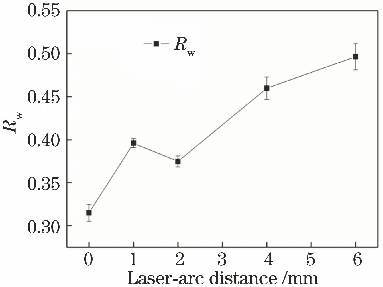
    Fig. 1. Back width ratio of the welding seam
    Reinforcement and back reinforcement of the welding seam
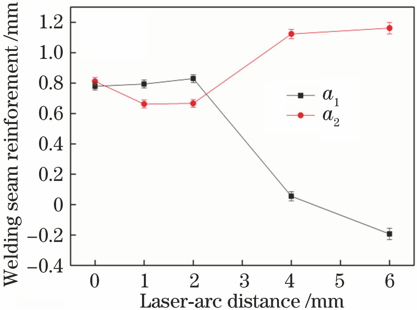
    Fig. 2. Reinforcement and back reinforcement of the welding seam
    XRD diagrams of base metal and welding seam. (a) Base metal; (b) welding seam
    Fig. 3. XRD diagrams of base metal and welding seam. (a) Base metal; (b) welding seam
    Microstructure of base metal
    Fig. 4. Microstructure of base metal
    Solidification mode and pseudo-binary phase diagram
    Fig. 5. Solidification mode and pseudo-binary phase diagram
    Cross-sectional morphology of the welding seam
    Fig. 6. Cross-sectional morphology of the welding seam
    Microstructures in different regions of the welding seam. (a) Ⅰ zone; (b) Ⅱ zone; (c) Ⅲ zone
    Fig. 7. Microstructures in different regions of the welding seam. (a) Ⅰ zone; (b) Ⅱ zone; (c) Ⅲ zone
    Microstructure in partial zone of the welding seam. (a) Skeletal δ-ferrite; (b) lathy δ-ferrite
    Fig. 8. Microstructure in partial zone of the welding seam. (a) Skeletal δ-ferrite; (b) lathy δ-ferrite
    Microhardness of the welding seam. (a) Upper part of the welding seam; (b) middle part of the welding seam; (c) lower part of the welding seam; (d) comparison of microhardness distribution in three regions
    Fig. 9. Microhardness of the welding seam. (a) Upper part of the welding seam; (b) middle part of the welding seam; (c) lower part of the welding seam; (d) comparison of microhardness distribution in three regions
    Tensile strength and elongation of welding seams under different laser-arc distances
    Fig. 10. Tensile strength and elongation of welding seams under different laser-arc distances
    SEM morphologies of stretch fracture. (a) Base metal; (b) welding seam
    Fig. 11. SEM morphologies of stretch fracture. (a) Base metal; (b) welding seam
    MaterialCMnPSSiCrNiMoNFe
    304 stainless steel0.071.030.0350.030.07518.308.240Bal.
    ER3080.041.850.0140.0080.3520.209.580.45Bal.
    Table 1. Mass fractions of the chemical compositions of base material and filler wire%
    Laser-arcdistance /mmWeldingspeed /(m·min-1)Wire feedingrate /(m·min-1)Laser power /kWArccurrent /AArcvoltage /V
    0 to 61.85.04.314720.3
    Table 2. Welding process parameters
    NumberWelding seam cross sectionWelding seam macroscopic morphology
    1-1 (DLA=0 mm)
    1-2 (DLA=1 mm)
    1-3 (DLA=2 mm)
    1-4 (DLA=4 mm)
    1-5 (DLA=6 mm)
    Table 3. Macroscopic and cross-sectional morphologies of welding seams under different laser-arc distances
    Limei Han, Detao Cai, Yupeng Zhang, Nannan Zhang. Influence of Laser-Arc Distance on Joint of 304 Stainless Steel by Laser-MIG Hybrid Welding[J]. Laser & Optoelectronics Progress, 2018, 55(6): 061407
    Download Citation