
Shuaijun Duan, Guihua Fan, Laixian Zhang, Ruifeng Liu. Laser-Echo-Power Distribution Model of Large-Field Cat-Eye Lens and Characteristics Analysis[J]. Acta Optica Sinica, 2019, 39(10): 1006001
- Acta Optica Sinica
- Vol. 39, Issue 10, 1006001 (2019)
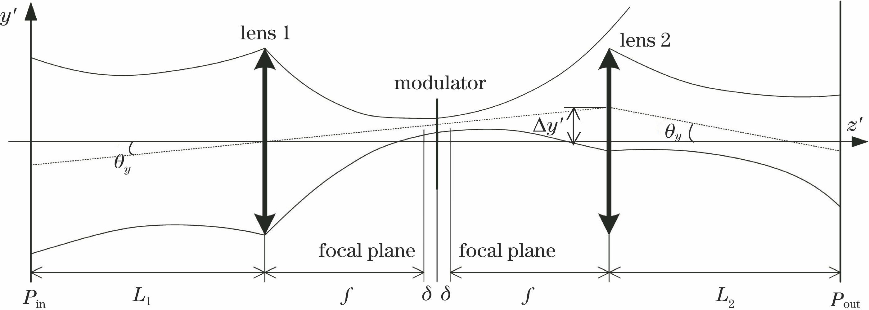
Fig. 1. Transmission process of tilting Gaussian beam passing through cat-eye optical lens
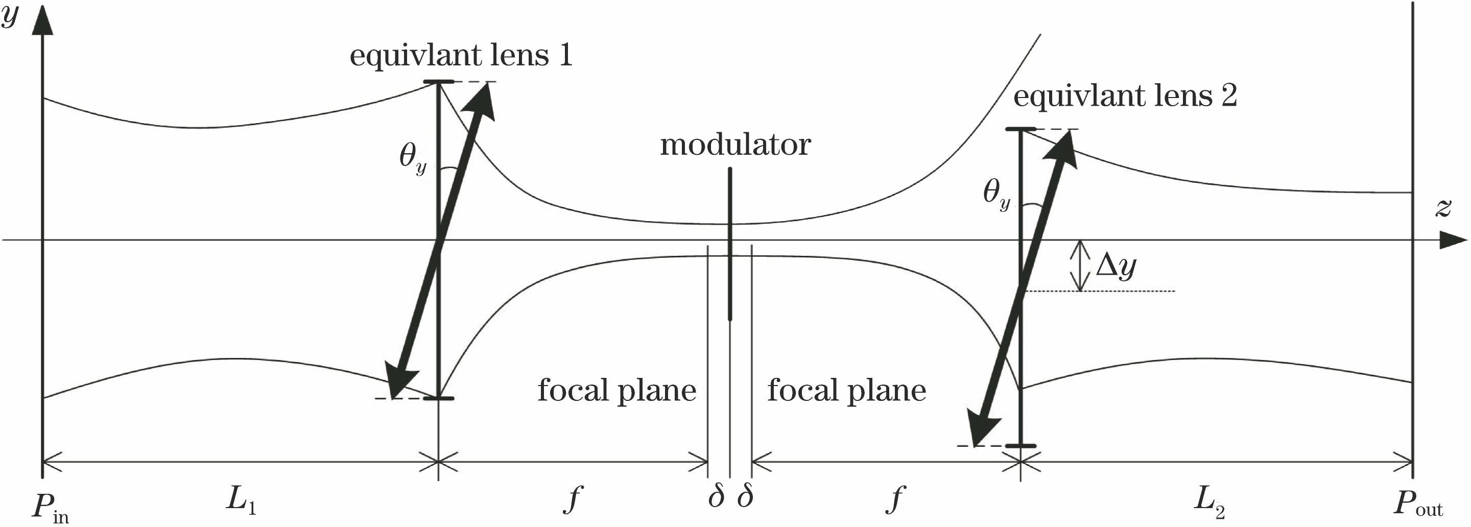
Fig. 2. Transmission process of equivalent normal incident beam passing through line misalignment cat-eye optical lens
Fig. 3. Echo spots and intensity distributions with different incident angles. (a)-(d) Echo spots when θ =0°,10°,20°,30°; (e)-(h) intensity distributions when θ =0°,10°,20°,30°
Fig. 4. Echo spots with different focal lengths when incident angle is 20° and diameter is 50 mm. (a) f =20 mm; (b) f =30 mm; (c) f =40 mm; (d) f =50 mm
Fig. 5. Echo spots with different diameters when incident angle is 20° and focal length is 50 mm. (a) D =50 mm; (b) D =60 mm; (c) D =70 mm; (d) D =80 mm
Fig. 6. Echo spots with different defocusing amounts at normal incidence. (a) δ =-0.02 mm; (b) δ =-0.01 mm; (c) δ =0 mm; (d) δ =0.01 mm; (e) δ =0.02 mm
Fig. 7. Echo spots with different defocusing amounts at incident angle of 20°. (a) δ =-0.02 mm; (b) δ =-0.01 mm; (c) δ =0 mm; (d) δ =0.01 mm; (e) δ =0.02 mm
Fig. 8. Relationship between offset and incident angle under different defocusing amounts
Fig. 9. Relationship between offset and defocusing amount at different incident angles
Fig. 10. Diagram of experimental setup
Fig. 11. Experimental spots with different defocusing amounts at normal incidence. (a) δ =-1 mm; (b) δ =-0.5 mm; (c) δ =0 mm; (d) δ =0.5 mm; (e) δ =1 mm
Fig. 12. Simulated spots with different defocusing amounts at normal incidence. (a) δ =-1 mm; (b) δ =-0.5 mm; (c) δ =0 mm; (d) δ =0.5 mm; (e) δ =1 mm
Fig. 13. Experimental spots under different incident angles. (a) θ =0°; (b) θ =2°; (c) θ =4°; (d) θ =6°; (e) θ =8°
Fig. 14. Simulated spots under different incident angles. (a) θ =0°; (b) θ =2°; (c) θ =4°; (d) θ =6°; (e) θ =8°
Fig. 15. Offset of echo at different incident angles

Set citation alerts for the article
Please enter your email address
© Copyright 2018-2021 | Chinese Laser Press. All Rights Reserved 沪ICP备15018463号-20