An optoelectronic oscillator (OEO) is a microwave photonic system that produces microwave signals with ultralow phase noise using a high-quality-factor optical energy storage element. This type of oscillator is desired in various practical applications, such as communication links, signal processing, radar, metrology, radio astronomy, and reference clock distribution. Recently, new mode control and selection methods based on Fourier domain mode-locking and parity-time symmetry have been proposed and experimentally demonstrated in OEOs, which overcomes the long-existing mode building time and mode selection problems in a traditional OEO. Due to these mode control and selection methods, continuously chirped microwave waveforms can be generated directly from the OEO cavity and single-mode operation can be achieved without the need of ultranarrowband filters, which are not possible in a traditional OEO. Integrated OEOs with a compact size and low power consumption have also been demonstrated, which are key steps toward a new generation of compact and versatile OEOs for demanding applications. We review recent progress in the field of OEOs, with particular attention to new mode control and selection methods, as well as chip-scale integration of OEOs.
An oscillator is a resonant device that produces a periodic oscillating signal without any input. Radio frequency (RF) or microwave signals with frequencies ranging from around 20 kHz to 300 GHz are one of the common examples of signals generated by oscillators that have been widely used in a variety of applications such as communication links, radar, medical treatment, remote sensing, radio astronomy, spectroscopy, and RF energy. Very low phase noise at high center frequencies is required in demanding applications. However, the generation of low-phase-noise RF/microwave signals at high center frequencies is challenging for conventional electronic oscillators.1 This is mainly caused by the low quality ()-factor of electronic oscillators at high center frequencies, since the spectral purity of an oscillator is directly related to its -factor. Electronic oscillators such as quartz oscillators only have high -factors at low frequencies ranging from around 10 to 100 MHz. RF/microwave signals in the GHz range are commonly obtained by multiplying the output of a MHz range high-performance quartz oscillator. However, a phase noise deterioration of dBc/Hz is introduced in the frequency multiplication process, where is the multiplication factor. As a result, the phase noise performance of the multiplied signals steadily degrades with increasing oscillation frequency.
An optoelectronic oscillator (OEO)1–3 is a simple and cost-effective microwave photonic system to produce RF/microwave signals with ultralow phase noise using a high--factor optical storage element such as a long optical fiber delay line2–4 or a high- optical resonator.5,6 The maximum achievable frequency of OEOs is determined by the bandwidth of optical and electrical devices in its cavity, which is as large as 100 GHz and beyond. At the same time, the phase noise performance does not increase with frequency. Thus, a low phase noise can be easily achieved at high center frequencies. Moreover, OEOs can also generate signals in both the RF/microwave and optical (around 200 THz) domains simultaneously. Due to these significant features, OEOs have been widely investigated in recent years among various applications where an RF or microwave signal is generated, processed, or received.
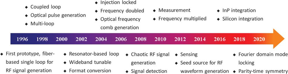
Figure 1 shows selected key developments in OEOs over the past 24 years. One of the main focus points of OEOs is their capability of generating continuous-wave RF/microwave signals with ultralow phase noise. Derived from the first fiber-based single-loop prototype proposed by Yao and Maleki2,3 in 1996, a series of architectures have been proposed and demonstrated to customize their performance. Coupled,7,25–28 multiloop,8,29–35 and injection-locked11,13,36,37 OEOs have been proposed in order to suppress the multimode oscillation in a single-loop OEO while maintaining a low phase noise. The use of high -factor resonators such as whispering gallery mode resonators (WGMRs)1,5,6 has also been demonstrated to mitigate the multimode oscillation problem in the fiber-based OEOs, with added benefits such as compact size and low operation power. For the frequency tunability of OEOs,9,17,38–51 the use of tunable electrical filters, optical filters, or microwave photonic filters (MPFs) instead of fixed electrical bandpass filters has been presented using yttrium iron garnet filters, a multi-tap architecture, a Fabry–Pérot laser diode (LD), a sliced broadband optical source and dispersive element, as well as phase-modulation to intensity-modulation (PM-IM) with the help of a phase-shifted fiber-Bragg grating, stimulated Brillouin scattering (SBS), dispersive elements, chirped fiber gratings, or asymmetric filtering. For example, a wide tunable range from dc to 60 GHz was obtained47 using an SBS-based filter. Moreover, frequency-doubled and frequency-multiplied OEOs12,17,52–58 have been proposed to further extend the frequency coverage of OEOs. High-frequency RF/microwave signals can be generated from these OEOs using low-frequency optoelectronic devices thanks to the use of specific modulators such as a polarization modulator (PolM) and a biased Mach–Zehnder modulator (MZM), as well as signal processing based on the SBS effect. At the same time, a phase noise deterioration of is also introduced in the frequency multiplication process. As a result, the phase noise of the frequency-doubled and frequency-multiplied microwave signals is higher than that of low-frequency microwave signals.
Sign up for Advanced Photonics TOC. Get the latest issue of Advanced Photonics delivered right to you!Sign up now
Figure 1.Selected key developments in OEOs over the past 24 years. The chronological order refers to the first date when it appeared in the literature. The concept of OEO was proposed by Yao and Maleki in 1996,2,3 where a fiber-based single-loop structure was demonstrated for the generation of single-frequency microwave signals. After that, there were the demonstrations of coupled OEO as well as optical pulse generation,7 multiloop8 OEO, resonators-based5 OEO, wideband frequency tunable OEO,9 format conversion,10 injection-locked OEO,11 frequency-doubled12 OEO, optical frequency comb generation,13 chaotic RF/microwave signal generation,14 signal detection,15 measurement,16 frequency-multiplied OEO,17 sensing,18 and OEO serving as a seed source to obtain RF/microwave waveforms.19 Recently, new mode control and selection methods based on FDML20 and PT symmetry21,22 have been proposed and demonstrated, which overcome the mode building time and mode selection problems in a traditional OEO. Integrated OEOs with compact size and low power consumption have also been demonstrated in InP23 and silicon24 platforms.
In addition to the capability of generating single-frequency microwave signals, OEOs have also been demonstrated to produce chaotic RF/microwave signals based on the dynamical behavior of OEO systems.14,59–63 Optical pulses7,25–28,64–68 and frequency combs13,69–71 have also been obtained using OEOs, since OEOs are able to provide both RF/microwave and optical outputs simultaneously. Using a seeded single frequency OEO, the generation of linearly chirped, phase-coded, triangular, and even arbitrary microwave waveforms has been demonstrated.19,72–74 In addition to signal generation, signal processing10,75–77 such as clock recovery and format conversion has also been demonstrated using OEOs. Furthermore, a large number of applications of OEOs to sensing, measurement, and detection have been developed15,16,18,78–91 to measure signals or specific parameters such as strain, temperature, refractive index, transverse load, distance, length change, position as well as RF/optical signals. The goal in these applications is to convert the target parameter or signal to the frequency change of the output electrical signals of OEOs. A high resolution is guaranteed due to the high resolution in the electrical frequency domain. Since the progress mentioned above is well summarized in other literature,63,92–96 we refer readers to these papers for a detailed overview of these topics.
In recent years, new mode control and selection methods, as well as chip-scale integration of OEOs, have been developed and have attracted considerable attention. Mode control based on Fourier domain mode-locking (FDML) breaks out of the limitation of mode building time in OEOs20,97–109 by synchronizing the tuning period of a frequency-scanning filter inside the OEO cavity to the cavity round-trip time. As a result, chirped microwave waveforms can be generated directly from the OEO cavity, which is not possible for conventional OEOs. A single-mode operation is achieved in a parity-time (PT) symmetric OEO,21,22,110–114 due to the mode selection based on PT symmetry using two feedback loops, with one having a gain and another having a loss of the same magnitude. Ultranarrowband filters are no longer needed for mode selection as in traditional OEOs. Moreover, with the rapid development of photonics integrated circuits (PICs), integrated OEOs23,24,115–120 with a small size and a low power consumption have also been demonstrated in indium phosphide (InP) and silicon platforms, which are key steps toward a new generation of compact and versatile OEOs for demanding applications.
In this paper, we highlight recent advances in the field of OEOs, with particular attention to the new mode control and selection methods as well as chip-scale integration of OEOs. The remainder of this paper is organized as follows. In Sec. 2, we provide the basic operation principle of OEOs. In Sec. 3, we discuss the mode control based on FDML, which allows the generation of chirped microwave waveforms directly from an OEO cavity. In Sec. 4, we review the mode selection based on PT symmetry to achieve single-mode oscillation without the need of high- filters. In Sec. 5, we discuss the integration of OEOs toward achieving a compact chip-scale device. Finally, we provide an outlook on this field in Sec. 6.
2 Working Principle of OEOs
An OEO has a hybrid positive feedback loop formed with an optical path and an electrical path that is capable of producing self-sustained oscillation signals. Figure 2 shows the schematic diagram of a typical single-loop OEO. As can be seen, a light wave from an LD is coupled to an electro-optic modulator (EOM) to generate several harmonics of the light frequency, then is amplified and sent to a long optical fiber to introduce a large -factor. A photodetector (PD) is used to convert the optical signal into the RF/microwave signal. The RF/microwave signal is amplified and filtered in the electrical path and fed back to the EOM to form a closed loop. A stable oscillation can be established from the noise if the overall gain exceeds the loss in the OEO cavity. The potential oscillation modes are determined by the cavity length of the OEO. In general, one mode is selected by the filter for a stable oscillation. It should be noted that the architecture of OEOs is flexible, which allows a variety of configurations with different elements to customize their performance. For example, the function of the electro-optic modulation can be realized by jointly using an intensity, phase or PolM, and a light source, or by using a directly modulated laser (DML).121 The high- cavity can be achieved with the help of a long fiber delay line, a WGMR, or a Fabry–Pérot resonator. The amplifier and filter can also be placed either in the optical path or the electrical path of the OEO loop. It should be noted that when using a phase or PolM in an OEO loop, the modulated signals should be converted to intensity modulated signals before photodetection, so a microwave signal can be generated at the output of the PD.
Figure 2.Schematic diagram of a typical single-loop OEO. It has a hybrid positive feedback loop formed with an optical path and an electrical path that is capable of producing self-sustained oscillation signals. LD, laser diode; EOM, electro-optic modulator; EDFA, erbium-doped fiber amplifier; PD, photodetector; EA, electrical amplifier.
The operation of OEOs can be analyzed mathematically based on the quasilinear theory developed by Yao and Maleki.2,3 In this model, the output signal of the electrical amplifier (EA) can be expressed as where is the input electrical signal of the EOM. and are the half-wave voltage and bias voltage of the EOM, respectively. determines the extinction ratio of the modulator . is the photon voltage at the output of the EA, where is the photocurrent at the PD, is the load impedance of the PD, is the gain of the EA, is the responsivity of the PD, is the insertion loss of the EOM, and is the input optical power.
Clearly, Eq. (1) describes the transmission of signals in the OEO loop from the input of the EOM to the output of the EA. According to Eq. (1), the open-loop gain of the OEO can be expressed as The magnitude of the open-loop gain must be larger than 1 for a self-sustained oscillation.
Equation (1) can be further linearized by assuming the electrical input signal of the EOM is a single-frequency sinusoidal wave, and the bandwidth of the filter is narrow enough to block all the harmonic components generated by the PD. In this case, the electrical input signal can be expressed as , where , , and are the amplitude, angular frequency, and initial phase of the input electrical signal, respectively. The linearized output of the electrical filter after one round trip of the OEO loop can be written as where is the voltage-gain coefficient defined as
Sign up for Advanced Photonics TOC. Get the latest issue of Advanced Photonics delivered right to you!Sign up now
In Eq. (4), denotes the first-order Bessel function. As can be seen from Eqs. (2) and (4), is also a function of frequency , since and are all frequency dependent. A unitless complex filter function is introduced to account for the effects of all the frequency-dependent components in the OEO loop in order to extract a frequency-independent factor , where is the real normalized transmission function and is the frequency-dependent phase. By doing so, Eq. (3) can be rewritten as where is the complex voltage in the OEO loop after times of circulation and is the time delay introduced by the physical length of the feedback loop. The initial complex voltage is the transient noise, where is the power density of the input noise and is the frequency bandwidth.
Once the oscillation is started from noise, the amplitude of the oscillation is increased until the gain is equal to unity, which would result in a stable oscillation. The total field can be expressed as the summation of all circulating fields. The stable output power can be written as where when the modulator is positively biased and when it is negatively biased. As can be seen from Eq. (6), the potential oscillation modes of the OEO are a series of frequency-periodic modes whose frequencies are determined by
The oscillating mode of the OEO is selected by the narrowband filter and generally only one mode is selected. According to Eq. (7), the oscillating frequency and free spectral range (FSR) of the OEO can be expressed as and where is the total cavity delay of the OEO loop.
In addition to the cavity modes, the phase noise performance is another important figure of merit of an oscillator. The single-sideband phase noise is just the power spectral density of an oscillator in most cases when the amplitude fluctuation is much smaller than the phase fluctuation. The power spectral density2,3 of the OEO can be calculated as where is defined as , which is the input noise-to-signal ratio of the OEO. is the total oscillating power and is the frequency offset from the oscillation peak . As can be seen from Eq. (10), the power spectral density of the oscillation mode is a Lorentz function whose full width at half-maximum (FWHM) is . Thus, the -factor of the OEO when the modulator is positively biased can be expressed as where is the -factor of the loop delay line.
As can be seen from Eqs. (10) and (11), the phase noise performance of the OEOs is related to the -factor and the noise-to-signal ratio that is determined by several factors such as the relative intensity noise and the frequency noise of the laser, the flicker noise and power handling capability of the PD, and the thermal noise of the amplifiers.92 A low phase noise can be obtained due to the very high -factor of the loop delay line. For instance, an ultralow phase noise of at a 6 kHz offset frequency was achieved in Ref. 4 using a long-fiber-based OEO operating at 10 GHz. Moreover, the phase noise performance is independent of the oscillation frequency. As a result, OEOs are perfect signal sources for the generation of high-frequency low-phase noise RF/microwave signals.
3 Fourier Domain Mode-Locked OEO
3.1 Mode Control Based on Fourier Domain Mode-Locking
As we mentioned above, RF/microwave signals with ultralow phase noise can be generated by OEOs due to the use of a high--factor energy storage element such as a long optical fiber delay line. However, a high--factor energy storage element would also result in a long mode building time that is related to the cavity round-trip time, since stable oscillations are build-ups from thermal noise in the OEO cavity. As a result, it is impossible to generate continuously chirped microwave waveforms directly from a traditional OEO cavity. Every new oscillation mode must build up repeatedly from noise in this case.
Recently we proposed and demonstrated a new mode control method based on FDML to generate continuously chirped microwave waveforms directly from an OEO cavity, which breaks out of the limitation of mode building time in traditional OEOs.20 The schematic diagram of the proposed Fourier domain mode-locked OEO (FDML OEO) is shown in Fig. 3(a). The basic idea is to incorporate a frequency-scanning filter rather than a statistical one, as in traditional OEOs, into the FDML OEO cavity and synchronize the tuning period of the filter to the cavity round-trip time to achieve FDML operation. In this operation, a number of modes are selected by the frequency-scanning filter, and the passband of the filter is tuned at the same frequency position when a mode travels back to it after each cavity round trip. All the selected modes are active simultaneously for an entire frequency sweep; thus, a continuously chirped microwave waveform is produced directly from the FDML OEO cavity.
As shown in Fig. 4(a), an MPF based on PM-IM conversion122–124 is used as the frequency-scanning filter in the experiment. The frequency-scanning MPF consists of a frequency-scanning LD, a phase modulator (PM), an optical notch filter, and a PD. The operation principle of the frequency-scanning MPF is as follows. Light waves from the LD are modulated by the microwave signals at the PM. No microwave signals would be detected if the phase-modulated light waves are applied directly to the PD, because the sidebands of the phase-modulated light waves have the same amplitude but opposite signs. With the help of the optical notch filter to remove one of the first-order sidebands of the phase-modulated light waves, a microwave signal can be detected by the PD. An equivalent MPF is achieved accordingly. The center frequency of the passband of the MPF is equal to the frequency difference of the LD and the optical notch filter. Clearly, a frequency-scanning MPF is achieved by sweeping the frequency of the LD, which is driven by a sawtooth current. The frequency-scanning MPF can be expressed as a “convolutional filter,” whose input and output signals are frequency downconverted and upconverted by the same local oscillation.20 Ignoring any noise, signals at the input and output of the MPF can be expressed mathematically as where and are the input and output chirped microwave signals, respectively, and is the center frequency. is the phase variation of the LD. is the impulse response of the filter when it is statistical. is the convolution operator. is the saturation factor of PM-IM conversion process, is an th-order Bessel function. In the FDML OEO, the scanning period of the MPF is synchronized with the round-trip time to achieve FDML operation where is the scanning period of the MPF and is an integer. If the OEO loop is closed, the frequency components in an entire frequency chirp would be returned to the MPF at the exact time when the MPF is scanned at the same spectral position. Every frequency component in the frequency chirp can be sustained simultaneously. The oscillation in the FDML OEO cavity would repeat itself after the loop round trip, which should satisfy
Figure 4.Experimental setup and generated signal of the FDML OEO.20 (a) The experimental setup. An MPF based on PM-IM conversion is used as the frequency-scanning filter in the experiment. The frequency-scanning MPF consists of a frequency-scanning LD, a PM, an optical notch filter, and a PD. (b) The spectrum of the generated X band (8 to 12 GHz) LCMW. (c) The details of the spectrum with a much smaller span. (d) The temporal waveform. (e) The instantaneous frequency–time diagram. (f) The compressed pulse by autocorrelation. Figures reproduced from Ref. 20, licensed under a Creative Commons CC BY license.
Thus, the stable oscillation signals of the FDML OEO satisfy where is the phase variation of the LD when FDML operation is satisfied. As can be seen from Eq. (15), a continuously chirped microwave waveform can be generated directly from the FDML OEO. The bandwidth and time duration of the generated chirped microwave waveform are equal to that of the LD, which can be easily reconfigured. Moreover, due to the large time delay provided by the FDML OEO cavity, the time duration of the generated chirped microwave waveforms is as long as tens of , which would result in an ultralarge time-bandwidth product (TBWP).
Figures 4(b)–4(e) show the spectra, temporal waveform, and instantaneous frequency–time diagram of the generated X band (8 to 12 GHz) linearly chirped microwave waveform (LCMW) based on the FDML OEO.20 As can be seen from Fig. 4(b), the frequency of the generated LCMW is from about 8 to 12 GHz, which covers the whole X band. Moreover, as can be inferred from the details of the spectrum shown in Fig. 4(c), all the modes of the FDML OEO in the X band are oscillating simultaneously. The frequency difference between the adjacent oscillation modes is equal to the driving frequency of the frequency-scanning filter, which is consistent with the FDML theory. As shown in the instantaneous frequency–time diagram in Fig. 4(e), the frequency of the generated LCMW is periodic and almost linearly increasing within one period. It should be noted that the bandwidth of the MPF can also influence the linearity of the generated LCMW since mode hopping is inevitable due to the large bandwidth (90 MHz) of the MPF used in our experiment. In applications such as modern radar systems, the range resolution would be deteriorated by the nonlinearity of the generated signals since they broaden the target beat frequency spectral width when deramping techniques are used. This problem could be relieved, for example, by using a filter with a narrower bandwidth to increase the linearity or by performing nonlinearity compensation. The TBWP of the generated X band LCMW is as large as 88,880, which is highly desired in radar applications. We also calculated the autocorrelation of the generated LCMW to demonstrate the pulse compression capability. A large pulse compression ratio of 80,800 is achieved. The bandwidth and center frequency of the FDML OEO can also be tuned by simply tuning the amplitude and DC bias of the driving signal of the LD, respectively. A maximum bandwidth of 7.5 GHz is achieved in the experiment, which corresponds to a large TBWP of 166,650. The maximum achievable frequency is as high as 18 GHz, which is only limited by the bandwidth of the PD used in our experiment.
In addition to the reconfigurable LCMW, the generation of the dual-chirp microwave waveform,102 phase-coded LCMW,103 frequency-doubled LCMW,104 and frequency-definable LCMW,105 as well as complementary LCMW pair,106 has also been demonstrated based on the FDML OEO. For example, in Ref. 102, we have proposed a dual-chirp FDML OEO using a frequency-scanning dual-passband MPF. As shown in Fig. 5, the MPF is based on PM-IM conversion by the use of an optical notch filter and two LDs. FDML operation is achieved by synchronizing the tuning period of the dual-passband MPF to the cavity round-trip time. Dual-chirp microwave waveforms with a tunable center frequency and bandwidth are generated directly from the dual-chirp FDML OEO cavity, which can be used in modern radar systems to cancel the unwanted range-Doppler coupling effect.
Modern radar systems are one of the typical application scenarios of the FDML OEO. FDML OEO-based radar systems can be implemented without the requirement of external RF sources since the required RF waveforms can be generated directly from the FDML OEO cavity. A reconfigurable microwave photonic radar system based on the FDML OEO has been proposed and experimentally demonstrated very recently.107Figure 6 shows the schematic diagram and target imaging results of the microwave photonic radar. In the microwave photonic radar, a microwave waveform with a large TBWP is generated by the FDML OEO at the transmitting end. Photonics-based dechirp processing is adapted at the receiving end. The bandwidth and center frequency of the radar are reconfigurable due to the tunability of the FDML OEO. A high resolution can also be obtained by virtue of the large TBWP of the FDML OEO. In the experiment, a pair of trihedral corner reflectors (TCRs) is used as the target. As can be seen from Fig. 6(c), a range resolution of 7.2 cm is achieved. The measured distances of the two TCRs are 34.8 cm in the range direction and 98.6 cm in the cross-range direction, which are in line with the real conditions. Therefore, the FDML OEO-based radar scheme has a great potential for developing multifunctional and reconfigurable high-resolution radar systems due to the reconfigurability and large bandwidth of the FDML OEO.
In addition to the generation of complex microwave waveforms, the FDML OEO can also be used for microwave photonic frequency-to-time mapping. The basic idea is to map the frequency of the unknown microwave signal to the time difference of the output pulses of the FDML OEO so the microwave spectral information can be measured in the time domain. Figure 7(a) shows the principle of operation of the FDML OEO-based frequency-to-time mapping system.108,109 A pair of pulses can be obtained at the output of the system when a single-tone microwave signal is injected into the FDML OEO cavity due to the bidirectional frequency-scanning properity of the FDML OEO. The time difference of the output pulses is related to the frequency of the injected microwave signal, so frequency-to-time mapping is achieved. Multiple pairs of output pulses can be obtained at the output when a multitone microwave signal is injected into the FDML OEO, so the proposed frequency-to-time mapping system is capable of measuring multitone microwave signals. This feature is highly desired in practical applications since various unknown frequency components may exist in the microwave signals under measurement.125,126 In the frequency-to-time mapping system, the FDML OEO can operate either around109 or above108 the threshold. When the FDML OEO is operated above the threshold, frequency-to-time mapping is established using an extra electrical filter to select a portion of the beat-note or sum-note between the unknown signal and the oscillation signal of the FDML OEO.108 When the FDML OEO is operated around the threshold, frequency-to-time mapping can be achieved directly from the FDML OEO cavity since oscillation is avoided when no unknown signal is injected.109 For the measurement of unknown multitone microwave signals, multiple pulses with different time intervals can be generated at the output. In order to avoid false frequency identification, the oscilloscope used to monitor the output of the system can be synchronized with the driving signal of the MPF. By doing so, we can focus on the output pulses within one frequency-scanning period of the FDML OEO, since the orders of the output pulses are determined by the frequencies of the input unknown signals, as shown in Fig. 7(a).
Figure 7(b) shows the measured pulse envelopes when a single-tone microwave singal with a different frequency is applied to the FDML OEO-based frequency-to-time mapping system. As can be seen, the time differences of the output pulse pairs are increased with the increasing of the applied frequency. The frequency of the single-tone microwave singal is measured based on the frequency-to-time mapping relationship established by the FDML OEO. Figure 7(c) shows the measured results and errors. The frequency measurement errors are no more than 60 MHz. The measurement range is only limited by the bandwidth of the PD used in the experiment, which can be easily extended to tens of GHz using large bandwidth optoelectronic deives. The ability to measure the unknown microwave frequency information in the time domain using the proposed frequency-to-time mapping method has the potential to ensure new microwave photonic metrology and signal processing approaches with a superior performance in terms of operation speed and real-time bandwidth.
4 Parity-Time Symmetric OEO
4.1 Parity-Time Symmetry for Mode Selection in OEO
In addition to a long-mode building time, the use of a high--factor energy storage element, such as a long optical fiber delay line, in OEOs would also result in closely spaced cavity modes. For example, if a 5 km optical fiber delay line is used, the frequency spacing of the two adjacent cavity modes is only 40 kHz. In general, narrowband electrical or optical filters and dual-loop structures are used in traditional OEOs in order to achieve a single-mode operation. However, narrowband electrical and optical filters are hard to achieve, especially at high center frequencies, and the loop length must be controlled precisely to maintain the conditions for the Vernier effect in the dual-loop structure. Recently, single-mode oscillation has been achieved in PT symmetric OEOs21,22 without using any narrowband optical/electrical filters, which overcomes the long-existing mode selection problem in traditional OEOs.
PT symmetry fundamentally exploits the fact that non-Hermitian operators can exhibit real eigenvalues associated with nonorthogonal eigenstates. By increasing the level of non-hermiticity, the symmetry can be broken after passing a so-called transition point, leading to nonreal eigenvalues.21,127–129 In particular, a coupled PT-symmetric structure using two identical feedback loops, with one having a gain and the other having a loss of the same magnitude, has been widely investigated as a powerful tool for cavity mode selection both in photonic130–135 and electronic136 cavities. An OEO is a microwave photonic system with a hybrid optoelectronic cavity, and it is natural to wonder whether a coupled PT-symmetric structure can be applied to OEOs for cavity mode selection.
In Refs. 21 and 22, we have proposed and experimentally demonstrated the use of PT symmetry for mode selection in an OEO with two mutually coupled feedback loops by precisely controlling the gain and loss in the two coupled loops. The simplified schematic diagram of a PT symmetric OEO is shown in the right part of Fig. 8(c). As can be seen, the PT symmetric OEO has a dual-loop structure, with one loop having a gain and the other having a loss of the same magnitude. Theoretically,21 the dynamic equations describing the interplay between the th longitudinal mode of the two coupled loops can be written as where and are the amplitudes of the th longitudinal modes in each loop. and represent the gain and loss of each loop, respectively. is the coupling efficient between the two coupled loops. is the angular frequency of the th longitudinal mode, are the resonance frequencies of each loop, and are the detuning frequencies of each loop. By focusing on the steady-state oscillation regime of the device, we can get the frequency eigenvalues of the supermodes of the system as follows:
Figure 8.PT symmetric phases in OEOs.21 (a) A traditional single-loop OEO oscillates without a narrowband filter. All longitudinal modes with a positive net gain will oscillate. (b) A traditional dual-loop OEO oscillates without narrowband filters. All longitudinal modes with a positive net gain will oscillate. (c) A PT symmetric OEO with two coupled loops oscillates under the PT broken phase condition. The gain and loss of each loop are balanced. By adjusting the gain, loss, and coupling efficient of the two loops, the loss can overcompensate the gain for all longitudinal modes except the one with the highest gain. As a result, a single-mode oscillation can be established at the longitudinal mode with the highest gain, while other modes will be suppressed. DPMZM, dual-polarization Mach–Zehnder modulator. Figures reproduced from Ref. 21, licensed under a Creative Commons CC BY license.
Assuming the loop lengths of the two coupled loops are the same, we have . Under the PT symmetry condition, which means the gain of one loop is equal to the magnitude of the loss in the other loop, i.e., , Eq. (18) can be simplified as
As can be seen from Eq. (19), the transition point is given by a gain/loss coefficient equal to the coupling coefficient . As a result, if , then the two loops oscillate at slightly different real frequencies. When , which is the PT broken phase condition, the frequency difference of the frequency eigenvalues becomes imaginary, thus a pair of amplifying and decaying modes is generated in each loop. A stable single-mode oscillation is achieved at the output of the gain loop in the PT symmetric OEO.
Figure 8 shows the different PT symmetric phases for a traditional single-loop OEO, a traditional dual-loop OEO, and a PT symmetric OEO. In a traditional filter-free single-loop OEO, all longitudinal modes with a positive net gain will oscillate. Narrowband optical/electrical filters are needed for a single-mode oscillation. The PT symmetric phases and oscillations in a traditional dual-loop OEO are similar to that of a traditional single-loop OEO. Multimode oscillation will occur if no optical/electrical filters are used. By tuning the gain and loss of the dual-loop OEO, and when the gain and loss of each loop are balanced, the dual-loop OEO will oscillate in the PT symmetry condition. By strictly adjusting the gain and loss of the two loops, the OEO will oscillate in the PT broken phase condition when the loss is higher than the coupling efficient between the two coupled loops. The loss overcompensates the gain for all of the longitudinal modes except for one mode with the highest gain, in this case. As a result, a single mode will emerge at the longitudinal mode with the highest gain, while other modes will be suppressed.
Figure 9(a) shows the schematic diagram of one of the designed PT symmetric OEOs using a polarization multiplexed modulator. The gain and loss of the PT symmetric OEO are controlled by tuning the gain of the erbium-doped fiber amplifier (EDFA) and the loss of the tunable attenuator (TA). We also used a tunable delay line (TDL) in order to eliminate the unwanted Vernier effect. Without PT symmetry, the OEO oscillates with the multimode. The measured multimode oscillation with a span of 2 GHz and a resolution bandwidth (RBW) of 100 kHz is shown in Fig. 9(b). By strictly tuning the gain and loss of the two coupled loops, a single-mode oscillation is achieved when the gain of one loop is equal to the loss of the other loop, and the loss is larger than the coupling coefficient between the two coupled loops. The measured single-mode oscillation is shown in Fig. 9(c). Almost at the same time, a PT symmetric OEO has also been proposed and experimentally demonstrated.22Figure 10 shows the schematic diagram and spectra of this PT symmetric OEO. A coupled dual-loop structure is achieved with the help of a balanced photodetector (BPD). A single-mode oscillation is also achieved when the PT symmetry condition and the PT broken phase condition are satisfied. These two pioneering works achieved single-mode oscillations without using any narrowband optical/electrical filters, which overcomes the long-existing mode selection problems in traditional OEOs.
Figure 9.Schematic diagram and spectra of a PT symmetric OEO using a polarization multiplexed modulator.21 (a) A block diagram of the PT symmetric OEO. (b) The multimode oscillation measured with a span of 2 GHz and an RBW of 100 kHz. (c) The single-mode oscillation measured with a span of 2 GHz and an RBW of 100 kHz. PC, polarization controller; MZM, Mach–Zehnder modulator; PR, polarization rotator; PBC, polarization beam combiner; SMF, single-mode fiber; TA, tunable attenuator; TDL, tunable delay line. Figures reproduced from Ref. 21, licensed under a Creative Commons CC BY license.
Figure 10.Schematic diagram and spectra of a PT symmetric OEO using a BPD.22 (a) A schematic digram of the PT symmetric OEO. (b) The multimode oscillation measured with a span of 100 MHz and an RBW of 3 MHz. (c) The single-mode oscillation measured with a span of 100 MHz and an RBW of 3 MHz. , microwave combiner. Figures reproduced from Ref. 22, licensed under a Creative Commons Attribution NonCommercial License 4.0 (CC BY-NC).
The frequency of the generated microwave signals is fixed in Refs. 21 and 22 since no frequency tuning mechanism is incorporated. In many applications, frequency tunable OEOs are preferred. Several approaches111–114 have also been proposed very recently to demonstrate frequency tunable PT symmetric OEOs using frequency tunable MPFs as a frequency tuning mechanism. For instance, a frequency tunable PT symmetric OEO based on a photonic integrated microdisk resonator (MDR) is proposed in Ref. 111. Figure 11 shows the schematic diagram and spectra of the frequency tunable PT symmetric OEO. As can be seen, a coupled dual-loop PT symmetric OEO, with one loop having a gain and the other having a loss of the same magnitude, is achieved by employing the reciprocity of light propagation in the MDR. A frequency tunable MPF based on PM-IM conversion is implemented in the PT symmetric OEO by the joint use of the PM and MDR. Coarse frequency selection is realized by thermally tuning the MDR. As can be seen from Fig. 11(c), the frequency of the PT symmetric OEO can be tuned from about 2 to 12 GHz.
Although a variety of OEO architectures have been proposed and demonstrated since it was first proposed in 1996, most of the reported OEOs are still implemented based on discrete optical and optoelectronic devices. These OEOs are bulky, expensive, and have a high-power consumption. For real world applications, it is highly desirable to integrating the whole OEO system on a chip. With the rapid development of PICs, integrated OEOs23,24,115–120 with small size and low power consumption have been demonstrated in InP and silicon platforms, which are key steps toward a new generation of compact and versatile OEOs for practical applications.
5.1 InP-Integrated OEO
Recently, we proposed and demonstrated an integrated OEO23,115 with monolithically integrated photonic parts on an InP substrate and RF parts on a print circuit board (PCB). Figure 12(a) shows the block diagram of the InP-integrated OEO. As can be seen, it has a simple single-loop structure consisting of an optical part and an electrical part. In the optical part, a DML is used to generate a light wave and achieve electro-optic modulation simultaneously. The modulated light wave is coupled into an optical delay line (ODL) for an increased time delay. The output optical signal of the ODL is converted into an electrical signal at the PD. In the electrical part, an electrical filter is used for mode selection. Electrical amplifiers are also used to ensure a self-sustained oscillation. Figure 12(b) shows the photograph of the InP-integrated OEO. As can be seen, the optical part is monolithically integrated on an InP substrate and the electrical part is fabricated on a PCB. The total size of the InP-integrated OEO is , which is as small as a coin. Due to the very compact size of the integrated OEO, the loop length is just several centimeters, corresponding to a large FSR of several GHz. As a result, the requirement of a narrowband filter for mode selection is greatly weakened. The 3 dB bandwidth of the electrical filter is about 7 GHz, which is good enough for single-mode oscillation in our integrated OEO.
The electrical spectra of the generated single-mode microwave signals are shown in Fig. 12(d). As can be seen, the frequency is tunable, which is achieved by tuning the injection current of the DML that leads to the tuning of the effective cavity length with the help of the dispersion effect. As can be seen, a frequency tuning range of around 20 MHz is achieved in the experiment. We also measured the phase noise performance of the generated microwave signal. As shown in Fig. 12(e), the phase noise is at a 1 MHz offset frequency. The phase noise performance is not as good as conventional fiber-based OEOs, which is caused mainly by the low -factor of the integrated OEO. Nevertheless, the InP-integrated OEO provides a proof of concept for the design of an operational device with a very compact size, which paves the way for future generations of integrated OEOs.
5.2 Silicon Integrated OEO
In addition to InP, today there coexists a wide diversity of other technology platforms to build PICs, such as silicon, silicon nitrides, lithium niobate, and polymers. Integrated microwave photonic systems including OEOs can benefit from these technology platforms.137–153 For example, a silicon photonic integrated OEO has been proposed and demonstrated24,116 recently. Figure 13(a) shows the perspective view of the silicon photonic integrated OEO. Three key components of the integrated OEO, including a high-speed PM, a thermally tunable high-selectivity MDR, and a high-speed PD, are integrated on a silicon photonic chip. The loop filter in the integrated OEO is a silicon photonic integrated MPF based on PM-IM conversion using the above three key components and an external LD. The closed integrated OEO loop is achieved by amplifying the output signal from the MPF and feeding it back to the input of the MPF. The oscillation frequency of the integrated OEO is determined by the central frequency of the passband of the MPF, which is equal to the frequency difference between the external LD and the frequency of the notch position of the MDR. By using the thermal-optic effect, the MDR could be thermally tunable, which eventually leads to the tuning of the frequency of the generated microwave signal of the integrated OEO. Figure 13(b) shows the measured electrical spectra of the generated microwave signals. As can be seen, the integrated OEO is capable of generating tunable microwave signals with a frequency tuning range from about 3 to 8 GHz. The phase noise performances of the generated microwave signals are also measured and are shown in Fig. 13(c). The phase noise is around at a 10 kHz offset frequency.
One key advantage of silicon photonics is its compatibility with the mature complementary metal oxide semiconductor (CMOS) technology. It is feasible to realize seamless integration between photonic parts and electronic circuits into the chip. A silicon-integrated OEO formed by hybrid-integration of a photonic chip and an electronic chip has also been reported in Ref. 117. Figure 14(a) shows the schematic diagram of the silicon-integrated OEO. As can be seen, all photonic and electronic building blocks of an OEO are integrated, except for the laser. The photonic chip consists of a grating coupler, a ring modulator, a dispersive ODL, and a PD. The output of the PD on the photonic chip is wire-bonded to the input of a trans-impedance amplifier (TIA) on the electronic chip. The output of the TIA is then split into two parts, one part is fed back to the ring modulator to form a closed OEO loop and is monitored by a spectrum analyzer and the other is used for optoelectronic frequency locking. The microphotograph of the hybrid-integrated optoelectronic feedback loop is shown in Fig. 14(b). Microwave oscillation is established in the OEO cavity when an external laser is coupled into the chip and the loop gain exceeds the loss. The measured spectrum and phase noise performance of the integrated OEO are shown in Figs. 14(c) and 14(d), respectively, when the OEO is locked to a reference RF source. The measured phase noise is about at a 100 kHz offset frequency. Although the oscillation frequency (about 1 GHz) is low compared with the above-mentioned integrated OEOs, the results demonstrate the great potential of the silicon technology for the implementation of fully integrated OEOs.
In addition to the examples aforementioned, integrated OEOs based on the on-chip SBS effect,118 integrated coupled structure,119 and silicon-microring resonator120 have also been proposed. In Ref. 118, a photonic chip-based integrated OEO scheme has been reported using a narrowband Brillouin MPF, which has the potential to be fully integrated. A model of hybridly integrated low phase noise-coupled OEO has been developed in Ref. 119, which can be used as a design tool for future integrated coupled OEOs. In Ref. 120, a silicon-integrated OEO scheme is proposed based on an add-drop ring resonator. Wideband frequency tuning is possible by changing the wavelength of the optical source or the resonance peak of the resonator.
6 Conclusions and Future Prospects
In this paper, we highlight recent progress in the field of OEOs, with particular attention to new mode control and selection methods based on FDML and PT symmetry, as well as chip-scale integration of OEOs. Continuously chirped microwave waveforms have been generated directly from the FDML OEO cavity, which breaks the mode building time limitation in a traditional OEO. The generation of a reconfigurable LCMW, a dual-chirp microwave waveform, a phase-coded LCMW, a frequency-doubled LCMW, a frequency-definable LCMW, and a complementary LCMW pair have been experimentally demonstrated, as well as FDML OEO-based microwave photonic radar and frequency-to-time mapping systems. We discussed mode selection based on PT symmetry in PT symmetric OEOs using two identical feedback loops with one having a gain and the other having a loss of the same magnitude. Single-mode operation is achieved without the need of ultranarrowband filters, which overcomes the long-existing mode selection problems in traditional OEOs. In addition to frequency-fixed PT symmetric OEOs, frequency-tunable PT symmetric OEOs have also been demonstrated with the help of tunable MPFs for coarse frequency selection. Finally, the demonstration of integrated OEOs in InP and silicon platforms has been reviewed. An InP-integrated OEO with monolithically integrated photonic parts and a silicon photonic integrated OEO with an integrated MPF, as well as a silicon-integrated OEO formed by hybrid-integration of a photonic chip and an electronic chip have been reported in recent years, which are key steps toward a new generation of compact and versatile OEOs for demanding applications.
OEOs are paradigmatic microwave photonic systems for the generation of RF/microwave signals. Various RF/microwave signals, including spectrally pure single-frequency signals, wideband chirped microwave waveforms, and chaotic oscillations have been obtained directly from the OEO cavity, due to the use of various mode control and selection methods. As a delay-line oscillator, the cavity modes of OEOs are a series of frequency-periodic modes whose frequencies are determined by the cavity delay. However, the amplitude and phase relationships of these modes are not bounded by the mode condition. It is still possible to produce other complex and even arbitrary microwave waveforms directly from an OEO cavity by selecting specific frequency components from all these potential cavity modes and controlling the relative amplitude and phase relationships between them. The FDML and PT symmetry are two last examples for mode control and selection in OEOs. We can still expect new advances in this area for the generation of different RF/microwave signals in the near future.154
Integrated OEOs with a compact size and low power consumption are highly desired in applications such as satellite communications and 5G networks, where they are expected to generate RF/microwave signals with a very low phase noise, for example below at a 10 kHz offset frequency. Although some prototypes have been demonstrated in InP and silicon platforms, their phase noise performances still do not meet the high requirements of practical applications. The large phase noise is mainly caused by the reduced -factor of the integrated OEOs. This problem could be solved by heterogeneous integration,137–146 where the -factor can be enhanced, for example, by using ultralow-loss silicon nitride waveguides155,156 or high- silicon nitride ring resonators.157 In addition, to achieve monolithic integration, the electrical parts and a laser must be integrated into the chip for the InP- and silicon-integrated OEO, respectively. One potential solution is to combine the strengths of InP-platforms and silicon photonics based on the rapidly developed InP membrane on-silicon technology158,159 to obtain a fully integrated chip, which contains all the active and passive building blocks of an OEO. On the other hand, silicon-based lasers160 may also be possible in the near future by modifying the electronic band structure of silicon and silicon-containing alloys,161 which may pave the way for the monolithically integrated silicon OEOs. Furthermore, all the integrated OEOs proposed and demonstrated recently have been based on a simple single-loop structure for the generation of single-frequency RF/microwave signals. It will be interesting to demonstrate other types of integrated OEOs with customized performances, such as an integrated FDML OEO using a frequency-scanning integrated filter for the generation of chirped microwave waveforms with increased frequency-scanning speed and an integrated PT symmetric OEO based on an integrated coupled dual-loop structure to achieve single-mode oscillation.
[12] T. Sakamoto, T. Kawanishi, M. Izutsu. Optoelectronic oscillator using push-pull Mach–Zehnder modulator biased at null point for optical two-tone signal generation, 877-879(2005).
[69] W. Li et al. Generation of flat optical frequency comb using a single polarization modulator and a Brillouin-assisted power equalizer. IEEE Photonics J., 6, 7900908(2014).
[101] R. Liu et al. Generating ultra-wideband LFM waveforms with large time duration based on frequency-sweeping optoelectronic oscillation, 1-3(2019).
[110] L. Li et al. A parity-time-symmetric optoelectronic oscillator based on dual-wavelength carriers in a single spatial optoelectronic loop, 1-4(2019).