• Chinese Optics Letters
  • Vol. 16, Issue 4, 041101 (2018)
Zhaodong Chen1, Rongwei Fan1, Guangchao Ye2, Tong Luo1, Jiayu Guan1, Zhigang Zhou1, and Deying Chen1、*
Author Affiliations
  • 1National Key Laboratory of Science and Technology on Tunable Laser, Harbin Institute of Technology, Harbin 150080, China
  • 2Heilongjiang Institute of Technology, Harbin 150050, China
  • show less
    DOI: 10.3788/COL201816.041101 Cite this Article Set citation alerts
    Zhaodong Chen, Rongwei Fan, Guangchao Ye, Tong Luo, Jiayu Guan, Zhigang Zhou, Deying Chen. Depth resolution improvement of streak tube imaging lidar system using three laser beams[J]. Chinese Optics Letters, 2018, 16(4): 041101 Copy Citation Text show less
    Schematic of the STIL system. (a) Schematic of the data collection process. (b) The work principle of the streak array detector. (c) The streak image on the CCD.
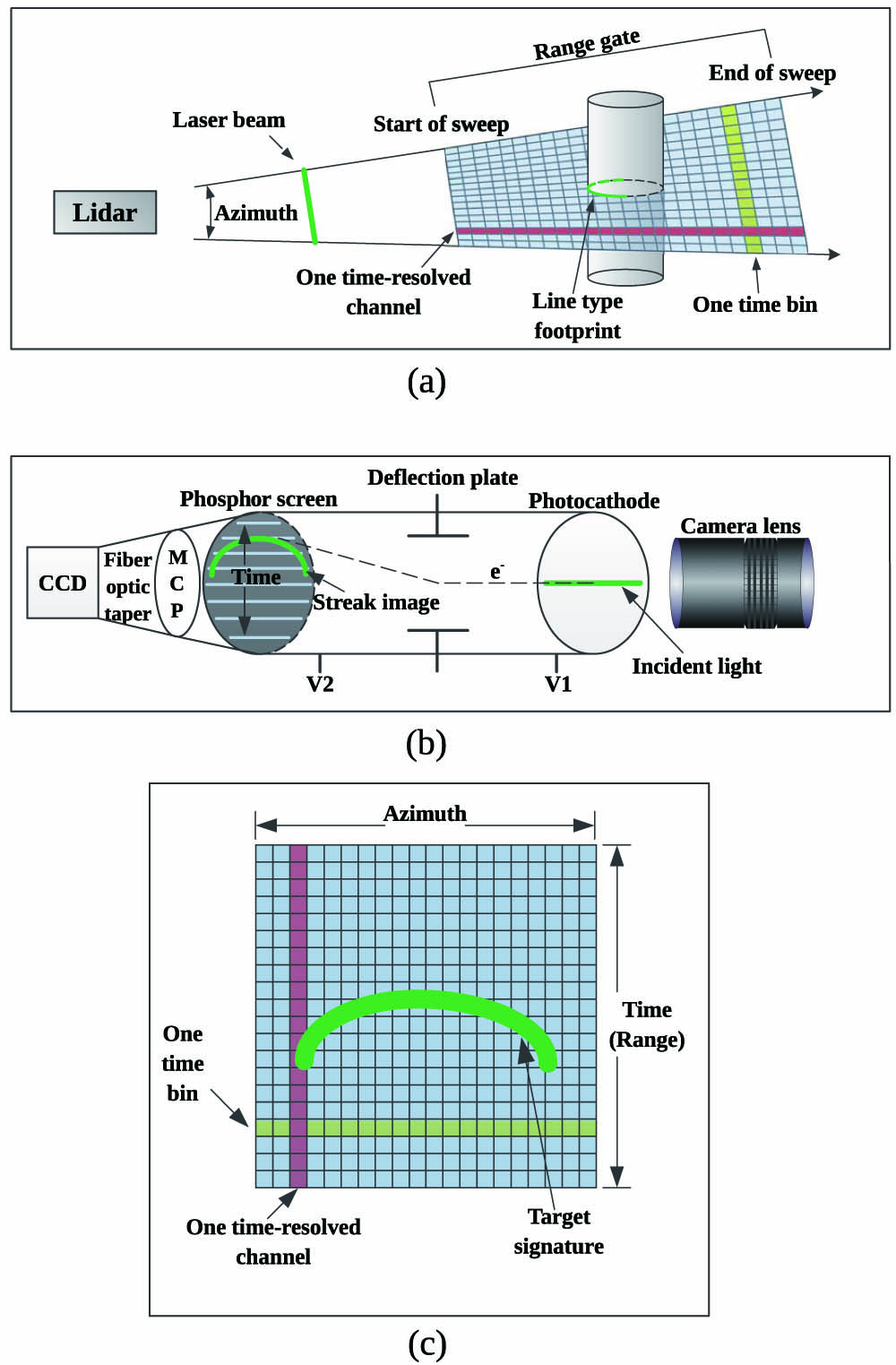
    Fig. 1. Schematic of the STIL system. (a) Schematic of the data collection process. (b) The work principle of the streak array detector. (c) The streak image on the CCD.
    Optical emission part of the three-laser-beam STIL system.
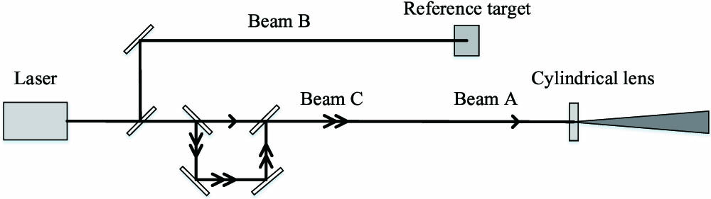
    Fig. 2. Optical emission part of the three-laser-beam STIL system.
    Streak image of a simple plane.
    Fig. 3. Streak image of a simple plane.
    Error between the calculated value and theoretical value.
    Fig. 4. Error between the calculated value and theoretical value.
    Distance error with the theoretical distance.
    Fig. 5. Distance error with the theoretical distance.
    (a) Schematic of the three-laser-beam STIL system. (b) The streak signal of Beam A, Beam B, and Beam C on the CCD.
    Fig. 6. (a) Schematic of the three-laser-beam STIL system. (b) The streak signal of Beam A, Beam B, and Beam C on the CCD.
    (a) Photograph of the model. (b) Size of the base. The unit is millimeters. (c) Heights of “H”, “I”, “T”, and “!”. They are 2, 5, 10, and 20 mm, respectively.
    Fig. 7. (a) Photograph of the model. (b) Size of the base. The unit is millimeters. (c) Heights of “H”, “I”, “T”, and “!”. They are 2, 5, 10, and 20 mm, respectively.
    Results of the 3D imaging experiment. Different colors are used to represent distances. (a) The image obtained using only Beam A, (c) the image obtained using Beam A and Beam B, and (e) the image obtained using Beam A, Beam B, and Beam C. (b), (d), and (f) are the cutaway drawings of (a), (c), and (e) near the blue line separately.
    Fig. 8. Results of the 3D imaging experiment. Different colors are used to represent distances. (a) The image obtained using only Beam A, (c) the image obtained using Beam A and Beam B, and (e) the image obtained using Beam A, Beam B, and Beam C. (b), (d), and (f) are the cutaway drawings of (a), (c), and (e) near the blue line separately.
    ParameterValue
    Wavelength of the laser532 nm
    Repetition rate of the laser1000 Hz
    Pulse width of the laser1 ns
    Power of the laser30mW
    CCD resolution(spatial-resolved × time-resolved)1000×500
    CCD grayscale0–255
    Time bin size, tbin0.066 ns
    Target distance6.98m
    Jitter of DG645<25ps
    Jitter of sweep voltages500ps
    Jitter of the laser output<400ps
    Field-of-view1.2°
    Table 1. Parameters of the STIL System
    Zhaodong Chen, Rongwei Fan, Guangchao Ye, Tong Luo, Jiayu Guan, Zhigang Zhou, Deying Chen. Depth resolution improvement of streak tube imaging lidar system using three laser beams[J]. Chinese Optics Letters, 2018, 16(4): 041101
    Download Citation