The work proposes a three-laser-beam streak tube imaging lidar system. Besides the main measuring laser beam, the second beam is used to decrease the error of time synchronization. The third beam has pixels’ difference compared to the main measuring beam on a CCD, and it is used to correct the error caused by CCD discrete sampling. A three-dimensional (3D) imaging experiment using this scheme is carried out with time bin size of 0.066 ns (i.e., corresponding to a distance of 9.9 mm). An image of a 3D model is obtained with the depth resolution of , which corresponds to .
The three-dimensional (3D) lidar technique has been widely used in a variety of fields, such as city construction, topographic mapping, underwater detection, and robotics[1–5]. Streak tube imaging lidar (STIL) is one of the main kinds of lidar. It has attracted a great deal of attention in recent years because of its high accuracy, wide field of view, and fast data rate[6–12].
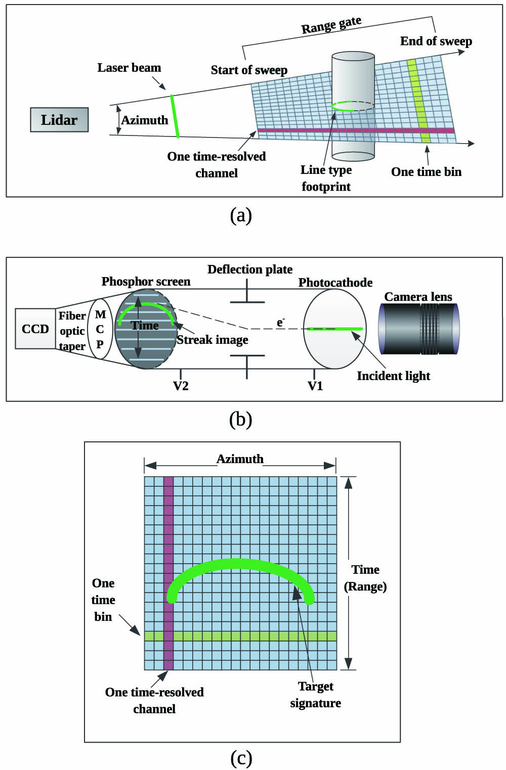
A typical schematic of the STIL system is shown in Fig. 1[13]. The laser is shaped into a fan beam by a cylindrical lens and forms a thin strip footprint on the target. The returned optical signal from the target is collected and imaged on the photocathode of the streak tube; then, the optical signal is converted into electrons. When the electron beam is accelerated to the phosphor screen by a high voltage, it will be deflected by a pair of linear sweep voltages. Finally, the electrons hit the screen of the streak tube and form a streak image. The signature position in the time-resolved channel on the screen is relative to the arrival time of the signal, i.e., we can obtain the target range from the image. Usually the images are intensified by a microchannel plate (MCP) and recorded by a CCD. The horizontal position represents the spatial information of the target, and the vertical position represents the range information.
Figure 1.Schematic of the STIL system. (a) Schematic of the data collection process. (b) The work principle of the streak array detector. (c) The streak image on the CCD.
Depth resolution is one of the most critical issues of a lidar system[14–21]. In this Letter, we propose a three-laser-beam STIL system to improve the depth resolution of the STIL system. The optical emission part of three-laser-beam STIL system is shown in Fig. 2.
Sign up for Chinese Optics Letters TOC. Get the latest issue of Chinese Optics Letters delivered right to you!Sign up now
Figure 2.Optical emission part of the three-laser-beam STIL system.
In essence, streak tube imaging is a process of measuring time-of-flight (TOF) of a laser pulse, so the timing control is crucial to the depth resolution. In a typical STIL system, the timing of the laser source, sweep voltages, MCP, and CCD are triggered by a timing control unit. Usually, timing jitters exist in the units mentioned above. The time gates of MCP and CCD are adopted to promote the signal-to-noise ratio (SNR), and the time jitters of their delays do not influence the depth resolution of the STIL system seriously if the signal can go through the time gates. However, the time jitters of the timing control unit, laser source, and sweep voltages influence the depth resolution significantly. According to the error transfer formula, the error caused by time jitter is given by where is the time jitter of the whole system, is the time jitter of the timing control unit, is the time jitter of the laser source, and is the time jitter of sweep voltages.
As shown in Fig. 2, Beam A is the main measuring beam to image the target, and Beam B is utilized to decrease the time jitters. Beam B is used to illuminate a reference target fixed on the STIL system. In every single signal period, the measured results of Beam A and Beam B have the same jitter, thus, we can use the obtained jitter of beam B to correct the results of Beam A for every signal period: where is the corrected distance, is the distance measured by Beam , and is the jitter of the distance measured by Beam B.
A simple experiment without a scan is carried out to prove that Beam B is beneficial for depth resolution. In the experiment, the target is a simple plane, the timing control unit is a digital delay generator (DG645, Stanford Research Systems Inc.) with the maximum jitter of 25 ps, the maximum jitter of laser source trigger to output is 400 ps, and the jitter of the sweep voltage is . With all conditions remaining the same, the streak signals obtained on the screen of the CCD have jitters. We measure the target for 50 times in the situation, and the result is shown in Fig. 3.
As shown in Fig. 3, if Beam B is not used to modify the streak image of Beam A, the standard deviation of the measurement result is 4.3 pixels. If we use Beam B to assist the measurement, the standard deviation is low at 0.3 pixel. It is obvious that the effect of Beam B on correcting errors caused by timing jitter is significant.
In general, the shape of the streak signal on the time-resolved axis can be approximated using a Gaussian function[19], where is the peak gray value of the streak signal, is the signal width, and is the center of the streak signal. Meanwhile, the theoretical distance can be calculated by where is the theoretical distance, is light speed in the air, is the TOF of the laser pulse, and is the time bin size.
For the th pixel, the gray value is the integral of in the interval , where is the gray value of the th pixel.
In general, we obtain the gray values and calculate the centroid on the time-resolved axis as the coordinate of the signal[19,20]: where is the calculated coordinate value of the signal on the time-resolved axis, and is the number of pixels on the time-resolved axis. Similarly, the calculated distance can be obtained by where is the calculated distance of the target.
Because of the pulse width of the laser, the width of the laser beam, the resolution of the optical receiving system, and the dispersion of streak tube and MCP, the streak signal has a size of several pixels on the CCD. The distance of the target is obtained by calculating the centroid of the streak signal on the time-resolved axis. Because the pixel is the minimum measurement unit of a CCD, and it cannot be separated, we cannot get the accuracy distance by calculating the centroid with a limited number of discrete gray values. There is an error between the calculated value and theoretical value, as shown in Fig. 4.
Figure 4.Error between the calculated value and theoretical value.
The error between the calculated distance of Beam A and the theoretical distance can be obtained by
To decrease the error caused by discrete sampling by the CCD, Beam C is utilized, as shown in Fig. 2. There is a preset optical path difference (OPD) between Beam C and Beam A, and the OPD leads to pixels’ difference between the two returned signals on the CCD: where is the OPD between Beam A and Beam C, and is a positive integer. The corrected distance is the mean value of the result measured by Beam A and Beam C, and the error can be obtained by Eq. (10). The simulation results are shown in Fig. 5,
In the simulation, , , , and the theoretical distance is 5.8–6.1 m. From Fig. 5, it can be seen that , , and vary with periodically, and the error of Beam A and the error of Beam C are almost opposite to each other, so mean value of them is close to zero. The standard deviation of and is 9.6 mm, and the standard deviation of is 0.1 mm. The results show that the error of the measured distance can be decreased to of the initial value using this solution. This method can improve the depth accuracy of the STIL system significantly. In addition, the mean of two measured results can reduce the random error.
Figure 5.Distance error with the theoretical distance.
To validate the feasibility of the three-laser-beam STIL system, an indoor 3D imaging experiment using the scheme is carried out, as shown in Fig. 6(a). The parameters of the system are shown in Table 1. A -switched solid-state laser is employed as the illumination source. The laser beam is divided into three beams: Beam A, Beam B, and Beam C. As stated above, Beam A is the main measuring beam, Beam B is used to decrease the jitter of the signal, and Beam C is utilized to correct the error caused by discrete sampling. The streak signals of the three beams are shown in Fig. 6(b).
The target is a model made by a 3D printer with the printing accuracy of 0.1 mm. There are some letters (“H”, “I”, “T”) and a punctuation mark (“!”) on a base plate, and their heights are 2, 5, 10, and 20 mm, respectively, as shown in Fig. 4(a). The main size of the model is shown in Figs. 7(b) and 7(c).
Figure 7.(a) Photograph of the model. (b) Size of the base. The unit is millimeters. (c) Heights of “H”, “I”, “T”, and “!”. They are 2, 5, 10, and 20 mm, respectively.
Using the three-laser-beam STIL system, the 3D image of the model is obtained. We present three processing results of the 3D imaging to compare the imaging quality obtained by one beam (Beam A), two beams (Beam A and Beam B), and three beams (Beam A, Beam B, and Beam C). Furthermore, the cutaway drawings of the three results are presented to study the quality intuitively. The results are shown in Fig. 8.
Figure 8.Results of the 3D imaging experiment. Different colors are used to represent distances. (a) The image obtained using only Beam A, (c) the image obtained using Beam A and Beam B, and (e) the image obtained using Beam A, Beam B, and Beam C. (b), (d), and (f) are the cutaway drawings of (a), (c), and (e) near the blue line separately.
As shown in Fig. 8, there are peaks on the left edge of the letters in the figures. It is due to the extreme change of the laser incident angle on the left edge. When the angle of incidence is zero, the returned light will be much stronger, and the streak signals will be saturated and distorted. Therefore, the range images deform on the edge of the letters. Because the outline of “!” is curved and not perpendicular to the incident light in most cases, there are no obvious peaks on the edge of “!”.
The distance of the base plate of the model is . Fig. 8(a) is the image obtained with only Beam A. It is obvious that the letter “H” in Fig. 8(a) cannot be separated from the base, and the quality of the other letters is very poor. The quality of Fig. 8(c) is much better than that of Fig. 8(a). Thus, it can be concluded that the depth resolution of the STIL system is improved significantly using Beam B. However, the image in Fig. 8(c) is rough, and the base plate and the letters contain many line-type concave and convex surfaces, which will influence the resolution of the image. The image of “H” in Fig. 8(e) is the clearest, and the outline of the cutaway drawing in Fig. 8(f) is the smoothest. Accordingly, Beam C can assist in improving the depth resolution. Using the three-laser-beam STIL system, the height of letter “H” can be separated from the base clearly. It means that this system has a resolution of .
In conclusion, this Letter proposes a three-laser-beam STIL system to improve depth resolution. The scheme can effectively decrease the timing jitter and errors caused by discrete sampling. The experimental results show that when the time bin size is 0.066 ns (i.e., corresponding to distance of 9.9 mm), the depth resolution is better than 2 mm, which corresponds to . The three-laser-beam STIL system is an effective approach to obtain high resolution 3D images.