
Jingtao Dong, Tengda Zhang, Lei Yang, Yuzhong Zhang, Rongsheng Lu, Xinglong Xie. Dark-field line confocal imaging with point confocality and extended line field for bulk defects detection[J]. Chinese Optics Letters, 2023, 21(4): 041203
- Chinese Optics Letters
- Vol. 21, Issue 4, 041203 (2023)
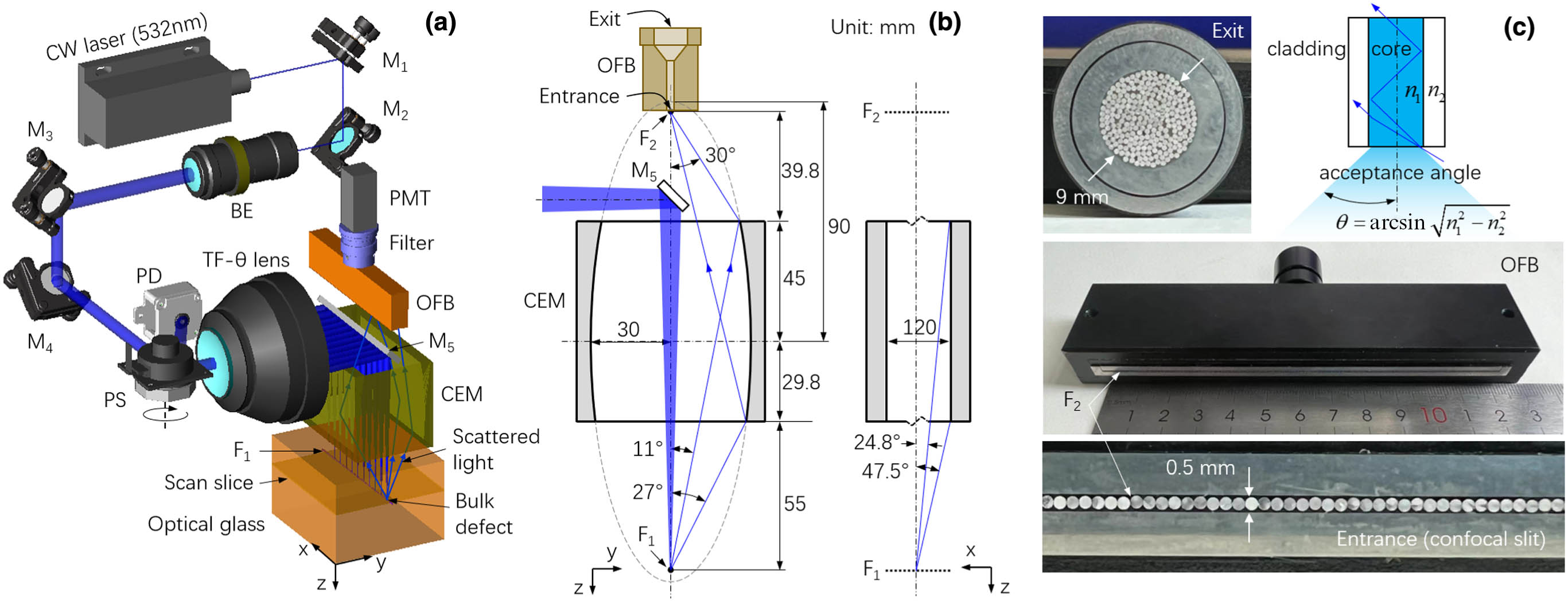
Fig. 1. (a) Schematic of the DF-LCI system; (b) principle of scattered light collection; (c) details of the OFB. M, mirror; BE, beam expander; PS, polygon scanner; PD, photodiode; TF-θ lens, telecentric F-θ lens; PMT, photomultiplier tube; OFB, optical fiber bundle; CEM, columnar elliptical mirror.
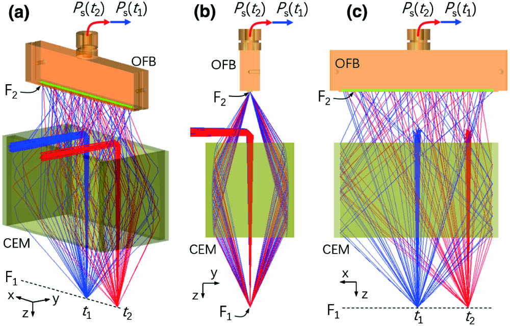
Fig. 2. Ray tracing results of the scattered light collector. (a) Stereo view; (b) side view; (c) front view. The blue and red rays correspond to the laser beams illuminating the bulk defects at adjacent moments, t1 and t2, respectively. The scattered light of the bulk defect is assumed to have a Lambertian distribution. For clarity of ray tracing, the blue and red rays corresponding to t1 and t2 are deliberately separated.
Fig. 3. (a) Illustration of the optical sectioning ability test; lower right inset, the home-made point source with a diameter of 10 µm; upper right inset, transverse optical sectioning ability test with a 5 µm diameter metal fiber scanning across the laser spot; measured OSTs in the (b) z direction; (c) x direction; and (d) y direction for different widths of the confocal slit.
Fig. 4. (a) Uniformity of the scattered light detection. The percentage shows the relative collection efficiency of the scattered light. (b) Uniformity of the axial and transverse optical sectioning abilities.
Fig. 5. (a) Rose fabricated inside a glass cube as the bulk defects using the laser microengraving technology; (b) dark-field image of a scan slice; (c) 3D reconstruction of the rose via the stack of dark-field images; inset, microscopic image of the bulk defects located at the leaves of the rose.

Set citation alerts for the article
Please enter your email address
© Copyright 2018-2021 | Chinese Laser Press. All Rights Reserved 沪ICP备15018463号-20