(TGG) is an excellent material for magneto-optical applications, and is the key component in Faraday isolators (FIs). The preparation process of transparent TGG ceramics is experimentally studied. The optical quality and the microstructure of the samples are investigated. The results show that the transmittance of the sample sintered at 1550°C is close to 72% in the region of 500–1500 nm. The Verdet constant at 632.8 nm measured at room temperature is , which is almost the same as that of a single crystal.
Faraday isolators (FIs) are fundamental optical devices for optical isolation and polarization control, and are frequently used in high-power lasers. The key component of such devices is a magneto-optical material placed in a constant magnetic field[1]. To date, the most commonly used crystalline Faraday magneto-optical material for 400–1100 nm (not including 470–500 nm) is the (TGG) single crystal[2]. Owing to the large Verdet constant, high thermal conductivity, and low transmission loss ()[3,4], the TGG single crystal has become the optimal material for FIs. Growing high quality TGG single crystals is not an easy task. The evaporation of from the melt during the crystal growth process is especially difficult[5]. Although much effort has been made to solve this problem and already some improvements have been achieved[6], challenges still remain. Fabricating transparent ceramics as magneto-optical materials to use in FIs is a possible solution for those problems. This method has the obvious advantages of convenient preparation, low cost, and large size (acceptable aperture). It is not necessary to involve melting to reduce the evaporation of [7]. As a result, transparent TGG ceramics have attracted great attention. A transparent TGG ceramic was first fabricated by Dr. Ikesue, and the possibility of its use in a high-power FI was reported in 2003[8]. The Faraday effect for TGG ceramics in a liquid nitrogen atmosphere was first observed by Yasuhara et al. in 2007[9]. The optical properties (laser-induced bulk damage threshold and optical scattering properties), Faraday effect, and the Verdet constant of a ceramic TGG at room temperature were reported in 2011. They were found to be similar to the counterparts of a TGG single crystal[10]. A large optical aperture TGG ceramic Faraday rotator (FR) with an isolation ratio of 33 dB was demonstrated at a laser radiation power of 257 W in 2014[11]. Thanks to the great efforts during the past ten years, the quality of TGG ceramics has been enhanced significantly. However, as far as we know, few publications reported the specific preparation process of transparent TGG ceramics. In this Letter, the preparation process of transparent TGG ceramics was experimentally studied. In the present work, transparent TGG ceramics have been prepared by a solid-state reaction and vacuum sintering. The range of the optimal sintering temperature of transparent TGG ceramics were discussed.
High-purity (99.99%) and powders were mixed according to the stoichiometric formulation with a 0.1 wt.% MgO as an additive. The powders were mixed and ball milled in absolute ethyl alcohol for 24 h with agate balls. Next, the powders were dried at 100°C for 24 h, sieved through a 200-mesh screen, uniaxially pressed into plates at 10 MPa, and then cold isostatically pressed at 200 MPa. The organic components of the green body are removed at 800°C in the muffle furnace for 3 h (pre-sintering). Transparent ceramics were obtained after sintering at 1500°C, 1550°C, and 1600°C under a base pressure of for 20 h. The obtained samples were named T1, T2, and T3, respectively. The ball-milled and dried powders mentioned above were directly sintered at 1100°C, 1200°C, and 1250°C in the muffle furnace. The X-ray diffraction (XRD) patterns showed that only the powder sintered at 1250°C exhibited a TGG phase. The powders with TGG phase were screened, uniaxially pressed, cold isostatically pressed, pre-sintered, and then sintered at 1550°C under a base pressure of for 20 h. The final specimen obtained was named T4. All the specimens (T1, T2, T3, and T4) were double side polished to the thickness of 1.0 mm.
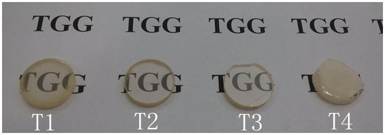
Figure 1.Photographs of the double side polished samples.
The phase and the structure of the powders and ceramic samples were characterized by XRD using an Ultima-IV diffractometer (Rigaku, Japan). The surface morphologies of the samples were taken by a JSM6360LA scanning electron microscope (SEM) (JEOL, Japan) and the optical transmittance spectra was measured with a V-570 UV IS/NIR spectrophotometer (JASCO, Japan). The porosity of the samples was observed by an optical microscope (OM) (BX-RLA2, OLYPMUS, Japan). The Verdet constant at 632.8 nm of the samples was measured by a homemade instrument consisting of a He–Ne laser, two polarizers, and an electromagnet.
Sign up for Chinese Optics Letters TOC. Get the latest issue of Chinese Optics Letters delivered right to you!Sign up now
Figure 1 shows a picture of the four samples(T1, T2, T3, and T4)after two-side mirror polishing. All of the samples exhibit transparency except for T4. Such a phenomenon indicated that converting the mixture powders into TGG phase in the muffle furnace first and then via vacuum sintering did not seem to be suitable for synthesizing TGG ceramics with high transparency.
The surfaces of the as-sintered samples T1, T2, and T3 were covered by a thin layer of bright yellow material after the vacuum sintering. Figure 2 shows the XRD patterns of the yellow shell, the powders sintering in the muffle furnace at 1250°C, and the four ceramic samples (T1, T2, T3, and T4). The results showed that the yellow shell was the mixed phases of TGG, , and , which may be due to the volatilization of . The powders sintered in the muffle furnace at 1250°C were of a pure TGG phase. For ceramics T1, T2, and T3, all of the peaks could be well indexed as the cubic structure of TGG.
Figure 3 shows the optical transmittance of the samples T1, T2, and T3. With the increase of the sintering temperature, the transmittance first increases and then decreases. From 500 to 1500 nm, the transmittance of T2 was close to 72%, which was the highest transmittance value of all the samples. When the sintering temperature was 1600°C, the transmittance of T3 dropped to 63%, which was lower than that of T2. When the sintering temperature was 1500°C, the transmittance of T1 was less than 60%. The results of Fig. 3 showed that the optical transmittance of the transparent TGG ceramics was sensitive to the sintering temperatures. The absorption of at 484 nm was observed. This was due to the transition[12–15]. The microstructures and their effects on the optical quality of the samples were investigated.
Figure 3.Optical transmittance of the ceramic samples T1, T2, and T3.
Figure 4 shows the SEM images (A1–C1) and the OM images (A2–C2) of T1, T2, and T3. The insert at the bottom-left corner shows the grain size distribution of T1, T2, and T3.The average grain size was determined by measuring the size of about 150 grains. The grain sizes were about 8.58, 10.47, and 14.74 μm for T1, T2, and T3, respectively. As shown in Fig. 4(A1), the grain size of the T1 is inhomogeneous and many pores can be seen in Fig. 4(A2). These residual pores act as the scattering center and greatly reduce the optical transmittance of T1. As seen in B1 of Fig. 4, the grain size is uniform, and no impurities are observed on the grain boundaries. The amount of pores in B2 of Fig. 4 was few compared with T1 and T3. When the sintering temperature was increased from 1550°C to 1600°C, the average grain size increased to 14.74 μm and the amount of pores increased again in T3 [see Figs. 4(C1) and 4(C2)]. It is clear that a high sintering temperature results in a high rate of the gain boundary migration and the fast growth of grains. During such a growth process, it is very easy to enclose the pores in the large grains. Table 1 gives the porosity of each sample[16]. The porosity can be calculated from the following equation: where is the measured average diameter of each pores in the fixed microscope sight field, while stands for the whole volume of the scanning area.
Figure 4.SEM morphology of the surface of T1 (A1), T2 (B1), and T3 (C1). Optical images showing pores of T1 (A2), T2 (B2), and T3 (C2).
Figure 5 shows a schematic of the experimental setup for measuring the Verdet constant at 632.8 nm of the TGG ceramic. A continuous wave (CW) laser passed through polarizer 1 and the transparent TGG ceramic sample that was located in the constant magnetic field in turn. The polarization plane of the laser light was rotated through the TGG ceramic by the Faraday effect. Polarizer 2 was adjusted until the power meter was at its lowest and the angle of rotation () was received. The Verdet constant is calculated by the expression below: where is the angle of rotation, is the intensity of magnetic field, is the thickness of the ceramic, and is the Verdet constant. The Verdet constant at 632.8 nm of the TGG ceramic sample was , which was close to the counterpart of the TGG single crystal[17].
Figure 5.Schematic diagram of the experimental setup for measuring the Verdet constant.
Transparent TGG ceramics can be prepared by a solid-state reaction and vacuum sintering. The range of the optimal sintering temperature is about 1500°C–1600°C. Our works also show that the transparent TGG ceramics cannot be obtained with good quality even under the appropriate sintering temperature when the powders are sintered into the TGG phase before the vacuum sintering. The Verdet constant at 632.8 nm of transparent TGG ceramics is , which is close to that of a TGG single crystal. Further investigation on the preparation of transparent TGG ceramics with high optical quality is ongoing.