• Advanced Photonics Nexus
  • Vol. 2, Issue 5, 056002 (2023)
Ximin Tian1, Yafeng Huang1, Junwei Xu1、*, Tao Jiang2, Pei Ding1, Yaning Xu1, Shenglan Zhang1, and Zhi-Yuan Li3、*
Author Affiliations
  • 1Zhengzhou University of Aeronautics, School of Materials Science and Engineering, Zhengzhou, China
  • 2Nanjing University, College of Engineering and Applied Sciences, National Laboratory of Solid State Microstructures, Nanjing, China
  • 3South China University of Technology, College of Physics and Optoelectronics, Guangzhou, China
  • show less
    DOI: 10.1117/1.APN.2.5.056002 Cite this Article Set citation alerts
    Ximin Tian, Yafeng Huang, Junwei Xu, Tao Jiang, Pei Ding, Yaning Xu, Shenglan Zhang, Zhi-Yuan Li. Differentiated design strategies toward broadband achromatic and polarization-insensitive metalenses[J]. Advanced Photonics Nexus, 2023, 2(5): 056002 Copy Citation Text show less
    Artistic rendering and design principles of the proposed BAPIML. (a) Schematic illustration of the BAPIML with broadband achromatic and polarization-insensitive functions. The MWIR beams with arbitrary polarizations are normally illuminated on the metasurface from the substrate side and the transmitted light with opposite helicity is achromatically converged at the same spot. The insets exhibit the top view of circular configuration of the BAPIML (left side) and the schematic diagram of the constituent elements of the BAPIML (right side). The meta-atom consists of two anisotropic GSST-based nanofins (NF1 and NF2) arranged orthogonally (orthogonal mode) or in parallel (parallel mode) to each other standing on the CaF2 substrate. The optimal structural parameters are p=3 μm, h=4.2 μm, L1=0.95 μm, W1=0.6 μm, L2=0.45 μm, and W2=1.65 μm, respectively. (b)–(d) Design principles of the proposed BAPIML: the diagram of overlapping process of two bright spots along the z axis. The cross-polarization transmittance (Tcross) in (e) and the corresponding PCE with respect to the wavelength in (f) for the selected nanofins of NF1 (black lines), NF2 (red lines), and their composite body NF1 and NF2 (blue lines). (g)–(i) Normalized magnetic intensity profiles for the selected nanofins of NF1, NF2, and their composite body NF1&NF2 along the x-cut (top panel) and y-cut (bottom panel) both at λ1=4 μm and λ2=5 μm, respectively.
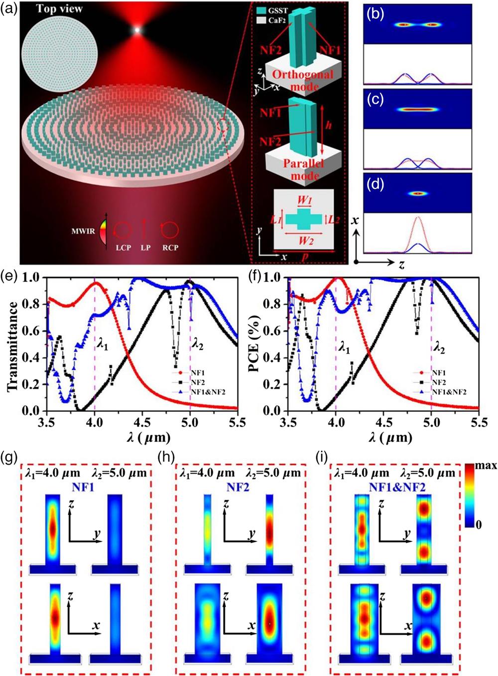
    Fig. 1. Artistic rendering and design principles of the proposed BAPIML. (a) Schematic illustration of the BAPIML with broadband achromatic and polarization-insensitive functions. The MWIR beams with arbitrary polarizations are normally illuminated on the metasurface from the substrate side and the transmitted light with opposite helicity is achromatically converged at the same spot. The insets exhibit the top view of circular configuration of the BAPIML (left side) and the schematic diagram of the constituent elements of the BAPIML (right side). The meta-atom consists of two anisotropic GSST-based nanofins (NF1 and NF2) arranged orthogonally (orthogonal mode) or in parallel (parallel mode) to each other standing on the CaF2 substrate. The optimal structural parameters are p=3  μm, h=4.2  μm, L1=0.95  μm, W1=0.6  μm, L2=0.45  μm, and W2=1.65  μm, respectively. (b)–(d) Design principles of the proposed BAPIML: the diagram of overlapping process of two bright spots along the z axis. The cross-polarization transmittance (Tcross) in (e) and the corresponding PCE with respect to the wavelength in (f) for the selected nanofins of NF1 (black lines), NF2 (red lines), and their composite body NF1 and NF2 (blue lines). (g)–(i) Normalized magnetic intensity profiles for the selected nanofins of NF1, NF2, and their composite body NF1&NF2 along the x-cut (top panel) and y-cut (bottom panel) both at λ1=4  μm and λ2=5  μm, respectively.
    Broadband achromatic focusing characterization of the BAPIML. The BAPIML was constructed with an NA=0.22 and a focal length of 400 μm. As control samples, the chromatic metalenses of ML1 and ML2 with the same NA and focal length were also designed. (a)–(c) Simulated intensity distributions in the x−z planes (bottom panels) and z-cut field profiles at focal planes (top panels) for the designed BAPIML, ML1 and ML2 under LCP incidence across the MWIR of 4 to 5 μm with a step of 0.1 μm, respectively. The insets (red solid lines) represent normalized intensity profiles along the white dashed lines of (a)–(c) for the three metalenses. The position of the dashed lines corresponds to the predefined focal length of 400 μm. (d) Simulated focal lengths and focal length shifts functioning versus wavelength for the designed BAPIML. The cases for the ML1 and ML2 are also given as comparisons. (e) The simulated peak intensities and FWHMs of focal spots as a function of the sampled wavelengths for the designed BAPIML. The pink dashed line denotes the corresponding theoretical diffraction limits. (f) The simulated focusing efficiencies and depth of focus of focal spots versus the sampled wavelengths for the designed BAPIML.
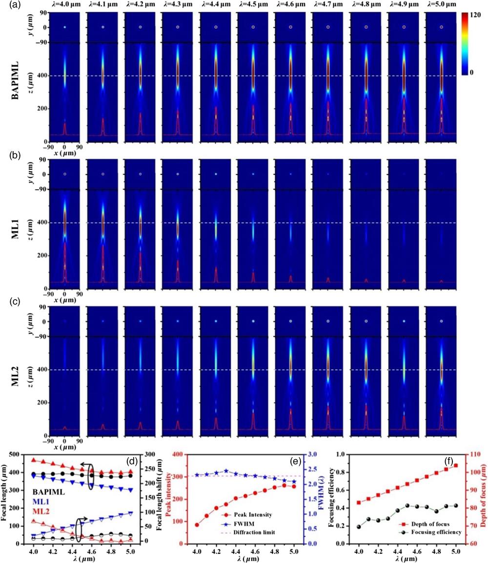
    Fig. 2. Broadband achromatic focusing characterization of the BAPIML. The BAPIML was constructed with an NA=0.22 and a focal length of 400  μm. As control samples, the chromatic metalenses of ML1 and ML2 with the same NA and focal length were also designed. (a)–(c) Simulated intensity distributions in the xz planes (bottom panels) and z-cut field profiles at focal planes (top panels) for the designed BAPIML, ML1 and ML2 under LCP incidence across the MWIR of 4 to 5  μm with a step of 0.1  μm, respectively. The insets (red solid lines) represent normalized intensity profiles along the white dashed lines of (a)–(c) for the three metalenses. The position of the dashed lines corresponds to the predefined focal length of 400  μm. (d) Simulated focal lengths and focal length shifts functioning versus wavelength for the designed BAPIML. The cases for the ML1 and ML2 are also given as comparisons. (e) The simulated peak intensities and FWHMs of focal spots as a function of the sampled wavelengths for the designed BAPIML. The pink dashed line denotes the corresponding theoretical diffraction limits. (f) The simulated focusing efficiencies and depth of focus of focal spots versus the sampled wavelengths for the designed BAPIML.
    Polarization-insensitive focusing performance of the BAPIML. Simulated intensity profiles in the x−z planes (bottom panels) and z-cut field profiles at the focal planes (top panels) for the designed BAPIML under linearly, circularly, and elliptically polarized lights at (a1) λ1=4 μm, (b1) λmid=4.5 μm, and (c1) λ2=5 μm, respectively. Herein LP0, LP45, and LP90 represent linearly polarized incident lights with electric vectors polarized in 0 deg, 45 deg, and 90 deg relative to the +x axis, and LEP and REP denote left-handed and right-handed elliptically polarized light with ellipticity of ±0.5, respectively. Simulated focal length and focal length shifts functioning versus the incident polarization states for the BAPIML at (a2) λ1=4 μm, (b2) λmid=4.5 μm, and (c2) λ2=5 μm, respectively. Simulated peak intensities and FWHMs of focal spots as a function of the incident polarization states for the designed BAPIML at (a3) λ1=4 μm, (b3) λmid=4.5 μm, and (c3) λ2=5 μm, respectively. The pink dashed lines denote the corresponding theoretical diffraction limits. The number on the abscissa represents the polarization angles of linearly polarized incident light and CP/EP represents circularly/elliptically polarized incident light.
    Fig. 3. Polarization-insensitive focusing performance of the BAPIML. Simulated intensity profiles in the xz planes (bottom panels) and z-cut field profiles at the focal planes (top panels) for the designed BAPIML under linearly, circularly, and elliptically polarized lights at (a1) λ1=4  μm, (b1) λmid=4.5  μm, and (c1) λ2=5  μm, respectively. Herein LP0, LP45, and LP90 represent linearly polarized incident lights with electric vectors polarized in 0 deg, 45 deg, and 90 deg relative to the +x axis, and LEP and REP denote left-handed and right-handed elliptically polarized light with ellipticity of ±0.5, respectively. Simulated focal length and focal length shifts functioning versus the incident polarization states for the BAPIML at (a2) λ1=4  μm, (b2) λmid=4.5  μm, and (c2) λ2=5  μm, respectively. Simulated peak intensities and FWHMs of focal spots as a function of the incident polarization states for the designed BAPIML at (a3) λ1=4  μm, (b3) λmid=4.5  μm, and (c3) λ2=5  μm, respectively. The pink dashed lines denote the corresponding theoretical diffraction limits. The number on the abscissa represents the polarization angles of linearly polarized incident light and CP/EP represents circularly/elliptically polarized incident light.
    Demonstration of the universality of our proposed design strategy. Simulated intensity profiles in the x−z planes (bottom panels) and z-cut field profiles at the focal planes (top panels) for another two BAPIML designs with different NAs and focal lengths. (a) is for the BAPIML with NA=0.263 and focal length is 440 μm; (b) is for the other BAPIML with NA=0.233 and focal length is 500 μm. The white dashed lines indicate the positions of the preset focal lengths.
    Fig. 4. Demonstration of the universality of our proposed design strategy. Simulated intensity profiles in the xz planes (bottom panels) and z-cut field profiles at the focal planes (top panels) for another two BAPIML designs with different NAs and focal lengths. (a) is for the BAPIML with NA=0.263 and focal length is 440  μm; (b) is for the other BAPIML with NA=0.233 and focal length is 500  μm. The white dashed lines indicate the positions of the preset focal lengths.
    Broadband achromatic focusing characterizations of the BAPIFOV. (a) Simulated intensity profiles along the axial plane within the overall designed waveband from 4 to 5 μm for the BAPIFOV under LCP incident light. (b) Simulated transverse intensity distributions and (c) phase profiles along the white dashed lines plotted in (a) for each sampled wavelength. (d) Simulated focal length versus the sampled wavelengths for the designed BAPIFOV. (e) Simulated horizontal cuts intensity profiles of the focal spots at the focal planes across the entire designed waveband from 4 to 5 μm for the BAPIFOV under LCP incident light. The hump-like field distributions along with intensity singularity (zero intensity) right in the center prove the focusing behavior of the vortex beam yield by the BAPIFOV metadevice. (f) Simulated FWHM spectra together with the theoretical diffraction limits versus the sampled wavelengths.
    Fig. 5. Broadband achromatic focusing characterizations of the BAPIFOV. (a) Simulated intensity profiles along the axial plane within the overall designed waveband from 4 to 5  μm for the BAPIFOV under LCP incident light. (b) Simulated transverse intensity distributions and (c) phase profiles along the white dashed lines plotted in (a) for each sampled wavelength. (d) Simulated focal length versus the sampled wavelengths for the designed BAPIFOV. (e) Simulated horizontal cuts intensity profiles of the focal spots at the focal planes across the entire designed waveband from 4 to 5  μm for the BAPIFOV under LCP incident light. The hump-like field distributions along with intensity singularity (zero intensity) right in the center prove the focusing behavior of the vortex beam yield by the BAPIFOV metadevice. (f) Simulated FWHM spectra together with the theoretical diffraction limits versus the sampled wavelengths.
    Polarization-insensitive characterization of the BAPIFOV. Simulated intensity profiles along the axial plane (bottom panel) and z-cut field profiles at the focal planes (top panels) for the BAPIFOV under linearly, circularly, and elliptically polarized incident lights at (a1) λ1=4 μm, (b1) λmid=4.5 μm, and (c1) λ2=5 μm, respectively. The white dashed lines indicate the positions of the preset focal lengths (500 μm). Simulated horizontal cuts intensity profiles of the focal spots at the focal planes for the BAPIFOV under all the sampled incident polarizations at (a2) λ1=4 μm, (b2) λmid=4.5 μm, and (c2) λ2=5 μm, respectively. Simulated focal lengths (red lines) and FWHMs (blue lines) of focal spots versus the incident polarizations for the designed BAPIFOV at (a3) λ1=4 μm, (b3) λmid=4.5 μm, and (c3) λ2=5 μm, respectively. The pink dashed line denotes the corresponding theoretical diffraction limits.
    Fig. 6. Polarization-insensitive characterization of the BAPIFOV. Simulated intensity profiles along the axial plane (bottom panel) and z-cut field profiles at the focal planes (top panels) for the BAPIFOV under linearly, circularly, and elliptically polarized incident lights at (a1) λ1=4  μm, (b1) λmid=4.5  μm, and (c1) λ2=5  μm, respectively. The white dashed lines indicate the positions of the preset focal lengths (500  μm). Simulated horizontal cuts intensity profiles of the focal spots at the focal planes for the BAPIFOV under all the sampled incident polarizations at (a2) λ1=4  μm, (b2) λmid=4.5  μm, and (c2) λ2=5  μm, respectively. Simulated focal lengths (red lines) and FWHMs (blue lines) of focal spots versus the incident polarizations for the designed BAPIFOV at (a3) λ1=4  μm, (b3) λmid=4.5  μm, and (c3) λ2=5  μm, respectively. The pink dashed line denotes the corresponding theoretical diffraction limits.
    Ximin Tian, Yafeng Huang, Junwei Xu, Tao Jiang, Pei Ding, Yaning Xu, Shenglan Zhang, Zhi-Yuan Li. Differentiated design strategies toward broadband achromatic and polarization-insensitive metalenses[J]. Advanced Photonics Nexus, 2023, 2(5): 056002
    Download Citation