
Zhiqiang Fang, Yao Yao, Kegui Xia, Jianlang Li. Simple Nd:YAG laser generates vector and vortex beam[J]. Chinese Optics Letters, 2015, 13(3): 031405
- Chinese Optics Letters
- Vol. 13, Issue 3, 031405 (2015)
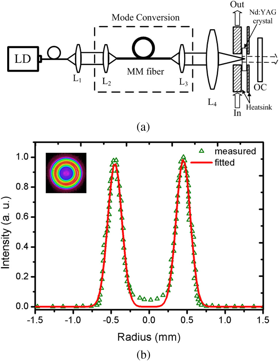
Fig. 1. (a) Schematic diagram of CW Nd:YAG laser by using annular pumping, and (b) captured intensity distribution of pumping light at L 4
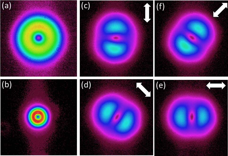
Fig. 2. (a) Far- and (b) near-field intensity distributions of the laser beam at 3.2 W pump power for CW Nd:YAG laser; (c)–(f) far-field intensity profiles of laser beam transmitted through the polarizer analyzer. The white arrows indicate the respective orientations of the polarizer analyzer’s axis.
Fig. 3. (a) Experimental setup of Mach–Zehnder interferometer and spiral interference patterns with (b) right handedness and (c) left handedness at an incident pump power of 3.2 W. M 1 M 2 L 1 f = 40 mm
Fig. 4. (a) Far- and (b) near-field intensity distributions of the laser beam at P abs = 3.8 W Q
Fig. 5. (a) Far- and (b) near-field intensity distributions of the laser beam; (c)–(f) variations of far-field intensity distribution of the passage beam through the polarizer analyzer with different orientations of the polarizer axes (where white arrows indict the directions of the polarizer analyzer’s axis); (g) measured spiral interference pattern with left handedness.

Set citation alerts for the article
Please enter your email address
© Copyright 2018-2021 | Chinese Laser Press. All Rights Reserved 沪ICP备15018463号-20