• Photonics Research
  • Vol. 9, Issue 2, 106 (2021)
Yan Liu1、†, Qing-Yun Yu1、†, Ze-Ming Chen1、†, Hao-Yang Qiu1, Rui Chen1, Shao-Ji Jiang1, Xin-Tao He1、2, Fu-Li Zhao1、3, and Jian-Wen Dong1、*
Author Affiliations
  • 1School of Physics & State Key Laboratory of Optoelectronic Materials and Technologies, Sun Yat-sen University, Guangzhou 510275, China
  • 2e-mail: hext9@mail.sysu.edu.cn
  • 3e-mail: stszfl@mail.sysu.edu.cn
  • show less
    DOI: 10.1364/PRJ.406197 Cite this Article Set citation alerts
    Yan Liu, Qing-Yun Yu, Ze-Ming Chen, Hao-Yang Qiu, Rui Chen, Shao-Ji Jiang, Xin-Tao He, Fu-Li Zhao, Jian-Wen Dong. Meta-objective with sub-micrometer resolution for microendoscopes[J]. Photonics Research, 2021, 9(2): 106 Copy Citation Text show less
    Schematics of microscope objectives for fiber bundle microendoscopes with different sizes and image qualities. (a) Plano–convex lens-based probe with centimeter diameter. (b) Graded index (GRIN) lens-based probe with millimeter diameter. (c) Probe based on the meta-objective with micrometer diameter, greatly reducing the size of the probe compared with (a) plano–convex lenses and (b) GRIN lenses. The dotted line enlarged section in (c) illustrates that meta-objective can eliminate monochromatic aberrations in full field of view (FOV) of both on- and off-axis, while the plano–convex lens and GRIN lens can only achieve on-axis aberration correction. The solid line magnified parts (rightmost) show the images transmitted through fiber bundles. Obviously, the use of the metalens-based objective produces aberration-free pictures.
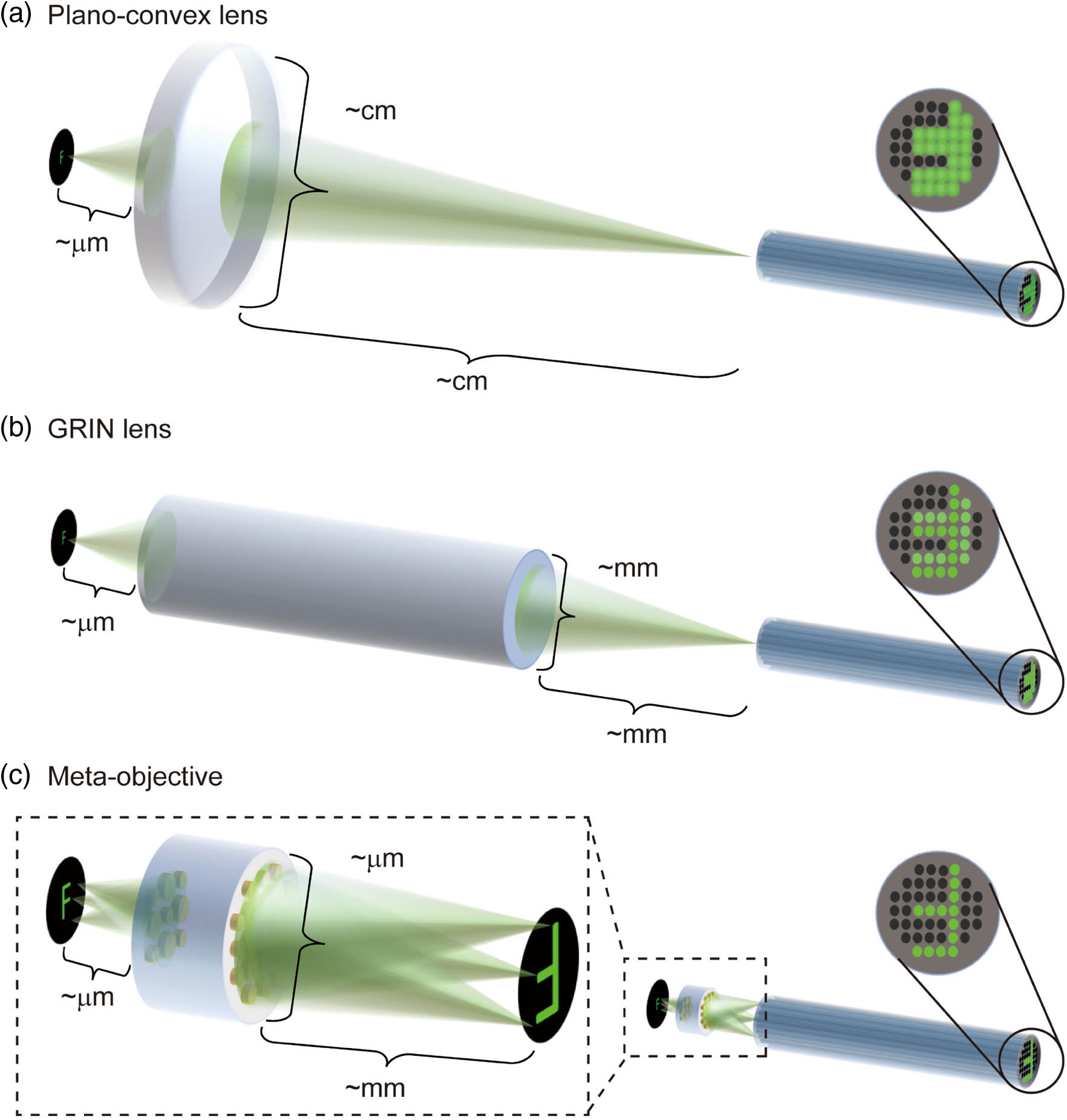
    Fig. 1. Schematics of microscope objectives for fiber bundle microendoscopes with different sizes and image qualities. (a) Plano–convex lens-based probe with centimeter diameter. (b) Graded index (GRIN) lens-based probe with millimeter diameter. (c) Probe based on the meta-objective with micrometer diameter, greatly reducing the size of the probe compared with (a) plano–convex lenses and (b) GRIN lenses. The dotted line enlarged section in (c) illustrates that meta-objective can eliminate monochromatic aberrations in full field of view (FOV) of both on- and off-axis, while the plano–convex lens and GRIN lens can only achieve on-axis aberration correction. The solid line magnified parts (rightmost) show the images transmitted through fiber bundles. Obviously, the use of the metalens-based objective produces aberration-free pictures.
    Ray optics design and sample of the meta-objective without monochromatic aberration. (a) Ray tracing simulation results of the single (top) and cascaded metalens (bottom) of 125 μm FOV at the working distance of 200 μm. The image heights of the single and cascaded metalens on the image plane are about 125 μm and 250 μm, respectively, due to their different magnifications. The blue/green/red rays (referring, respectively, to three normalized FOVs, 0.0 F, 0.5 F, and 1.0 F) have three crossing points at the same image plane in the cascaded case, compared to that of the single case. The three normalized FOVs correspond to on-axis, 62.5 μm FOV, and 125 μm FOV, respectively. (b), (c) Spot diagrams of three normalized FOVs for the two metalenses. The diffuse spot in 1.0 F (blue) is outside/inside the Airy circle (black solid) for the single/cascaded case, respectively. Similar behaviors appear in 0.5 F (green). It indicates that the cascaded metalenses have predominate advantage of eliminating monochromatic aberrations in the full FOV. (d) The calculated normalized intensity distribution of the meta-objective for 0.0 F along the propagation direction in the y-z plane at λ=525 nm. Schematic of a meta-atom of the cascaded metalens, consisting of a silicon nitride nanopost on a silica substrate. (e) The nanoposts with the height of 610 nm are arranged in a square lattice with the lattice constant of 380 nm for metalens I, while the corresponding values are 600 and 360 nm for metalens II. The diameters (D) of the nanoposts are variable according to phase distributions. (f), (g) Optical images and side-view SEM images (insets) of the two metalenses.
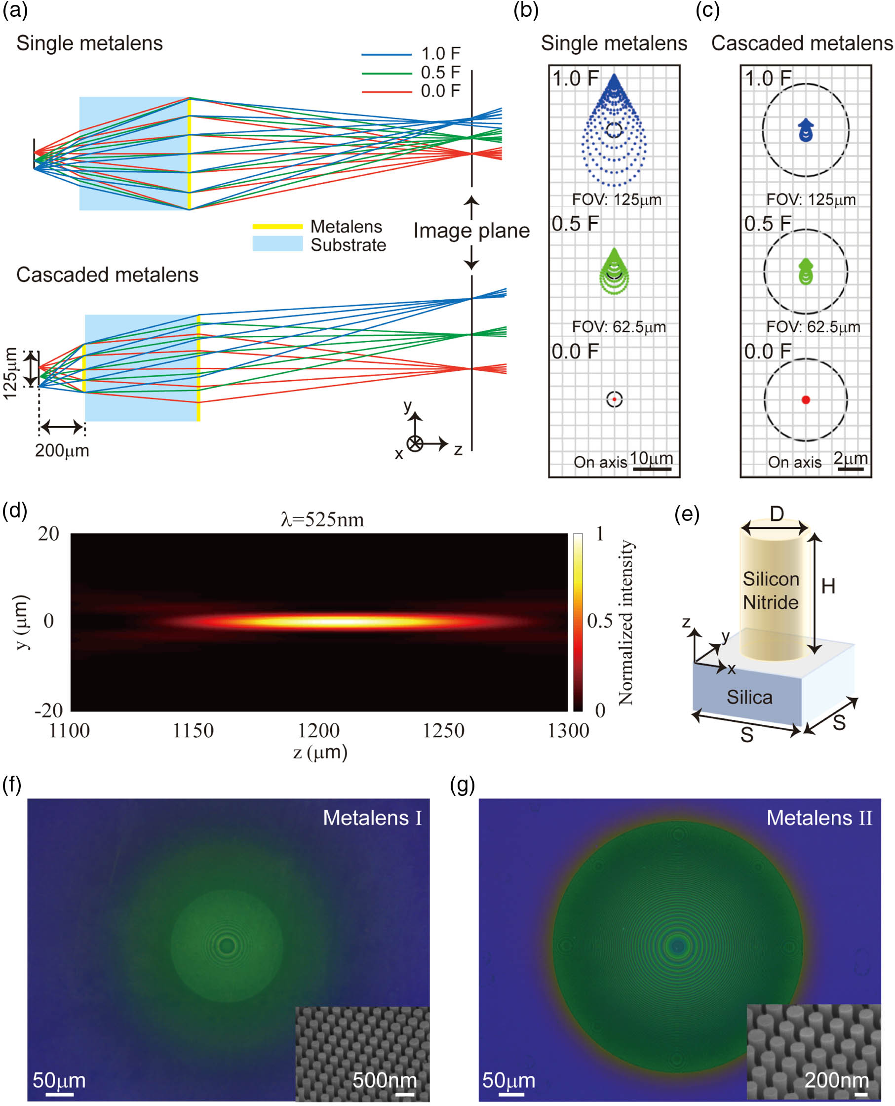
    Fig. 2. Ray optics design and sample of the meta-objective without monochromatic aberration. (a) Ray tracing simulation results of the single (top) and cascaded metalens (bottom) of 125 μm FOV at the working distance of 200 μm. The image heights of the single and cascaded metalens on the image plane are about 125 μm and 250 μm, respectively, due to their different magnifications. The blue/green/red rays (referring, respectively, to three normalized FOVs, 0.0 F, 0.5 F, and 1.0 F) have three crossing points at the same image plane in the cascaded case, compared to that of the single case. The three normalized FOVs correspond to on-axis, 62.5 μm FOV, and 125 μm FOV, respectively. (b), (c) Spot diagrams of three normalized FOVs for the two metalenses. The diffuse spot in 1.0 F (blue) is outside/inside the Airy circle (black solid) for the single/cascaded case, respectively. Similar behaviors appear in 0.5 F (green). It indicates that the cascaded metalenses have predominate advantage of eliminating monochromatic aberrations in the full FOV. (d) The calculated normalized intensity distribution of the meta-objective for 0.0 F along the propagation direction in the y-z plane at λ=525  nm. Schematic of a meta-atom of the cascaded metalens, consisting of a silicon nitride nanopost on a silica substrate. (e) The nanoposts with the height of 610 nm are arranged in a square lattice with the lattice constant of 380 nm for metalens I, while the corresponding values are 600 and 360 nm for metalens II. The diameters (D) of the nanoposts are variable according to phase distributions. (f), (g) Optical images and side-view SEM images (insets) of the two metalenses.
    Near diffraction limit sub-micrometer resolution characterization of the meta-objective at different incident wavelengths. (a) Simulated and measured focal spot diagrams and focal spot intensity profiles in 0.0 F, 0.5 F, 1.0 F of the meta-objective at 525 nm wavelength. The measured focal spot is 4 times magnified relative to the incidence point source. The experimental results of focal spots are in good agreement with their simulation results. The focal spots in 0.5 F and 1.0 F are similar to the focal spot in 0.0 F in size, indicating the performance of the meta-objective to eliminate monochromatic aberration. Fitting with Airy function, the full widths at half-maximum (FWHMs) of the measured focal spots along the x direction are 3.30 μm for 0.0 F, 3.41 μm for 0.5 F, and 3.62 μm for 1.0 F. (b) Corresponding to (a), the MTF curves in 0.0 F, 0.5 F, 1.0 F obtained by experiments. MTF curves in three fields of view are close to the MTF curve of the diffraction limit (black dotted line), further illustrating the high-resolution performance of the meta-objective. (c) Resolution tests by imaging a negative 1951 United States Air Force (USAF) target at wavelengths of 430 nm, 525 nm, and 680 nm. For 525 nm, the element 3 in group 9 (645 lp/mm, 0.775 μm linewidth, yellow line) and element 1 in group 9 (512 lp/mm, 0.977 μm linewidth, blue line) both have a contrast ratio of more than 20%, indicating that the meta-objective can resolve sub-micrometer details. Similar properties are also shown for 430 nm, 680 nm, and other more incident wavelengths.
    Fig. 3. Near diffraction limit sub-micrometer resolution characterization of the meta-objective at different incident wavelengths. (a) Simulated and measured focal spot diagrams and focal spot intensity profiles in 0.0 F, 0.5 F, 1.0 F of the meta-objective at 525 nm wavelength. The measured focal spot is 4 times magnified relative to the incidence point source. The experimental results of focal spots are in good agreement with their simulation results. The focal spots in 0.5 F and 1.0 F are similar to the focal spot in 0.0 F in size, indicating the performance of the meta-objective to eliminate monochromatic aberration. Fitting with Airy function, the full widths at half-maximum (FWHMs) of the measured focal spots along the x direction are 3.30 μm for 0.0 F, 3.41 μm for 0.5 F, and 3.62 μm for 1.0 F. (b) Corresponding to (a), the MTF curves in 0.0 F, 0.5 F, 1.0 F obtained by experiments. MTF curves in three fields of view are close to the MTF curve of the diffraction limit (black dotted line), further illustrating the high-resolution performance of the meta-objective. (c) Resolution tests by imaging a negative 1951 United States Air Force (USAF) target at wavelengths of 430 nm, 525 nm, and 680 nm. For 525 nm, the element 3 in group 9 (645 lp/mm, 0.775 μm linewidth, yellow line) and element 1 in group 9 (512 lp/mm, 0.977 μm linewidth, blue line) both have a contrast ratio of more than 20%, indicating that the meta-objective can resolve sub-micrometer details. Similar properties are also shown for 430 nm, 680 nm, and other more incident wavelengths.
    Different magnification imaging and biological imaging tests of the meta-objective. (a) Four times magnification imaging of letter “F” at wavelengths of 430 nm, 525 nm, and 680 nm. (b) The magnification graph of the meta-objective as a function of object distance. The experimental results (blue hollow circles) agree well with the simulation curve (red solid line). The insets are the corresponding images of letter “F” obtained in the experiment with different scale bars. (c) Imaging of water lily leaf slice and Bacillus cereus slice with the meta-objective, plano–convex lens, and GRIN lens, respectively. The yellow dotted boxes represent the cell wall of the water lily leaf’s mesophyll tissue. More depth information about the cell wall was obtained with the meta-objective, while only the outline could be distinguished with a GRIN lens, and the more blurred image was acquired with the plano–convex lens. The white and red dotted boxes indicate the gaps between the communities of Bacillus cereus. Similarly, the tiny spacing between bacterial groups can be identified with meta-objective, not obvious enough with a GRIN lens, and totally indistinguishable with a plano–convex lens.
    Fig. 4. Different magnification imaging and biological imaging tests of the meta-objective. (a) Four times magnification imaging of letter “F” at wavelengths of 430 nm, 525 nm, and 680 nm. (b) The magnification graph of the meta-objective as a function of object distance. The experimental results (blue hollow circles) agree well with the simulation curve (red solid line). The insets are the corresponding images of letter “F” obtained in the experiment with different scale bars. (c) Imaging of water lily leaf slice and Bacillus cereus slice with the meta-objective, plano–convex lens, and GRIN lens, respectively. The yellow dotted boxes represent the cell wall of the water lily leaf’s mesophyll tissue. More depth information about the cell wall was obtained with the meta-objective, while only the outline could be distinguished with a GRIN lens, and the more blurred image was acquired with the plano–convex lens. The white and red dotted boxes indicate the gaps between the communities of Bacillus cereus. Similarly, the tiny spacing between bacterial groups can be identified with meta-objective, not obvious enough with a GRIN lens, and totally indistinguishable with a plano–convex lens.
    Fiber bundle microendoscope with a meta-objective. (a) Schematic of the measurement setup. A customized 30-cm-long fiber bundle of more than 3900 fiber cores with a core diameter of 8 μm was employed here, combined with optical lenses for use as the probes of fiber bundle microendoscopes. (b) Resolution tests by imaging a negative 1951 USAF target using the fiber bundle microscope imaging system. The resolvable linewidths are 2.19 μm (element 6 in group 7, 228 lp/mm) with the meta-objective, 8.77 μm (element 6 in group 5, 57 lp/mm) with the plano–convex lens, and 4.39 μm (element 6 in group 6, 114 lp/mm) with the GRIN lens. The intrinsic resolution of the system without a lens is 12.41 μm (elements 3 in group 5, 40 lp/mm), provided as a reference. (c) Imaging of biological slice (water lily). Compared with the image directly transmitted through the fiber bundle only, the resolution is improved after introducing optical lenses as objectives placed in front of the fiber bundle. The orange arrows and the white arrows indicate the mesophyll cells and the cell wall, respectively. A more realistic image can be obtained with the meta-objective, while the image acquired with a GRIN lens will be distorted and even worse with the plano–convex lens. The displayed pictures in (b) and (c) are processed with the image post-processing technique to improve visualization.
    Fig. 5. Fiber bundle microendoscope with a meta-objective. (a) Schematic of the measurement setup. A customized 30-cm-long fiber bundle of more than 3900 fiber cores with a core diameter of 8 μm was employed here, combined with optical lenses for use as the probes of fiber bundle microendoscopes. (b) Resolution tests by imaging a negative 1951 USAF target using the fiber bundle microscope imaging system. The resolvable linewidths are 2.19 μm (element 6 in group 7, 228 lp/mm) with the meta-objective, 8.77 μm (element 6 in group 5, 57 lp/mm) with the plano–convex lens, and 4.39 μm (element 6 in group 6, 114 lp/mm) with the GRIN lens. The intrinsic resolution of the system without a lens is 12.41 μm (elements 3 in group 5, 40 lp/mm), provided as a reference. (c) Imaging of biological slice (water lily). Compared with the image directly transmitted through the fiber bundle only, the resolution is improved after introducing optical lenses as objectives placed in front of the fiber bundle. The orange arrows and the white arrows indicate the mesophyll cells and the cell wall, respectively. A more realistic image can be obtained with the meta-objective, while the image acquired with a GRIN lens will be distorted and even worse with the plano–convex lens. The displayed pictures in (b) and (c) are processed with the image post-processing technique to improve visualization.
    Yan Liu, Qing-Yun Yu, Ze-Ming Chen, Hao-Yang Qiu, Rui Chen, Shao-Ji Jiang, Xin-Tao He, Fu-Li Zhao, Jian-Wen Dong. Meta-objective with sub-micrometer resolution for microendoscopes[J]. Photonics Research, 2021, 9(2): 106
    Download Citation