
Zhenmin Zhu, Shuang Pei, Shiming Chen, Fumin Zhang. Highlight Removal of High Reflectivity Workpiece and Vision Measurement Based on Polarization Information[J]. Acta Optica Sinica, 2018, 38(11): 1112005
- Acta Optica Sinica
- Vol. 38, Issue 11, 1112005 (2018)
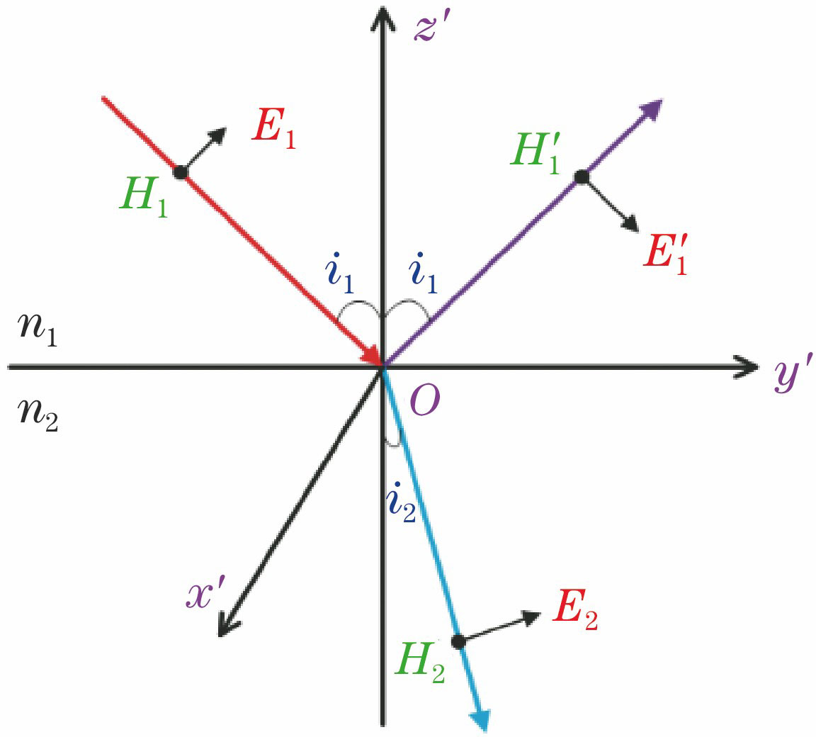
Fig. 1. p type polarization light
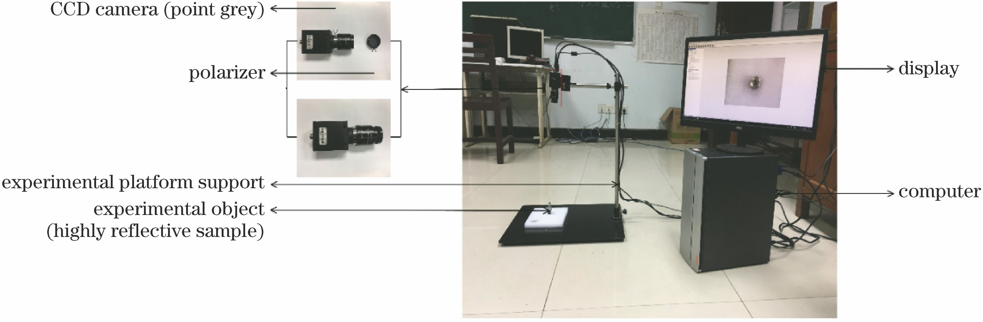
Fig. 2. Image acquisition system for vision measurement based on polarization device
Fig. 3. Image acquisition on object surface under different polarization angles
Fig. 4. White balance processing of image and corresponding histogram features. (a) Color image; (b) histogram of color image; (c) white balanced image; (d) histogram of white balanced image
Fig. 5. Flowchart of mean-shift segmentation algorithm based on dark channel images
Fig. 6. Images acquired under different polarization angles, image with highlight components and pixel luminance distribution in two-color reflection model
Fig. 7. BP neural network model for highlight removal based on polarization information
Fig. 8. Flowchart of image highlight removal based on polarization information
Fig. 9. Effect of image highlight removal based on polarization information. (a) Image acquired under optimal polarization angle; (b) pixel luminance distribution corresponding to (a); (c) image after highlight removal; (d) pixel luminance distribution corresponding to (c)
Fig. 10. Detail comparison of SIFT feature extraction. (a) SIFT feature extraction of image under optimal polarization angle; (b) SIFT feature extraction of image under optimal polarization angle after treatment by RANSAC algorithm; (c) SIFT feature extraction of image after highlight removal; (d) SIFT feature extraction of image after highlight removal and treatment by RANSAC algorithm
Fig. 11. Detail comparison of SURF feature extraction. (a) SURF feature extraction of image under optimal polarization angle; (b) SURF feature extraction of image under optimal polarization angle after treatment by RANSAC algorithm; (c) SURF feature extraction of image after highlight removal; (d) SURF feature extraction of image after highlight removal and treatment by RANSAC algorithm
Fig. 12. Boundary contours extracted under different conditions. (a) After highlight removal; (b) under optimal polarization angle
Fig. 13. Three-dimensional space coordinates of feature points of experimental object’s contour
| |||||||||||||||||||||||||||||||||||||||||||||||
Table 1. Number of feature points on workpiece surface under different conditions
|
Table 2. Coordinates of feature points for Sobel edge detection and corresponding world coordinates
|
Table 3. Comparison of measurement accuracy based on image highlight removal

Set citation alerts for the article
Please enter your email address
© Copyright 2018-2021 | Chinese Laser Press. All Rights Reserved 沪ICP备15018463号-20