Author Affiliations
1Department of Postgraduates, Changchun Institute of Optics, Fine Mechanics and Physics, University of Chinese Academy of Sciences, Changchun, Jilin 130033, China2First Department of Space Optics, Changchun Institute of Optics, Fine Mechanics and Physics, Chinese Academy of Sciences, Changchun, Jilin 130033, China3Department of Photoelectric Detection, Changchun Institute of Optics, Fine Mechanics and Physics, Chinese Academy of Sciences, Changchun, Jilin 130033, Chinashow less
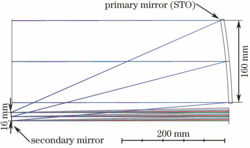
Fig. 1. Optical diagram of common aperture system
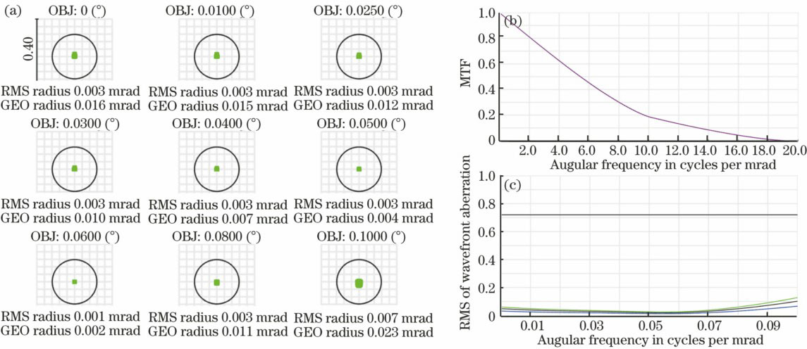
Fig. 2. Performance analysis diagram of common aperture system. (a) Spot radius; (b) diagram of MTF curve; (c) diagram of wavefront aberration
Fig. 3. Diagram of signal light transmitting optical structure and performance analysis. (a) 1550 nm transmitting system; (b) spot radius; (c) diagram of wavefront aberration
Fig. 4. Diagram of bacon light transmitting optical structure and performance analysis. (a) 1550 nm transmitting system; (b) spot radius; (c) diagram of wavefront
Fig. 5. Diagram of optical receiving structure
Fig. 6. Performance analysis diagram of signal light receiving system. (a) Diagram of spot radius; (b) diagram of wavefront; (c) diagram of MTF
Fig. 7. Diagram of bacon light receiving system
Fig. 8. Performance analysis diagram of tracking and pointing system. (a) Spot diagram; (b) energy concentration curve
Transmitting system of signal light | Transmitting system of beacon light |
---|
Wavelength /nm | ObjectNA | Divergence /mrad | Effectiveaperture /mm | Wavelength /nm | Object NA | Divergence /mrad | Effectiveaperture /mm | 1550 | 0.28 | ±1 (±0.06°) | 16 | 808 | 0.31 | ±1 (±0.06°) | 16 |
|
Table 1. Design parameters of transmitting system
Effective aperture /mm | Reduction ratio | Divergence for full-field /mrad |
---|
160 | 10∶1 | 2 (0.12°) |
|
Table 2. Design parameters of optical antenna
Wavelength /nm | Field of view /mrad | Imaging NA | Effective aperture /mm |
---|
1550 | ±1 (±0.06°) | 0.28 | 16 |
|
Table 3. Design parameters of signal light receiving system
Wavelength /nm | Size of entrancepupil /mm | Trackingaccuracy /μrad | Reduction ratio | Field of view | |
---|
| Coarsetracking /mrad | Finetracking /mrad |
---|
808 | 16 | 2 | 10∶1 | ±1 (±0.06°) | ±0.1 (±0.006°) |
|
Table 4. Design parameters of beacon light receiving system
Displacement | Primary mirror | Secondary mirror |
---|
Decenter X /mm | 0.025 | 0.025 | Decenter Y /mm | 0.025 | 0.025 | Decenter Z /mm | 0.025 | 0.025 | Tilted X /(″) | 20 | 60 | Tilted Y /(″) | 20 | 60 | Tilted Z /(″) | 20 | 60 |
|
Table 5. Optical antenna tolerance analysis
Displacement | STO | Surface 2 | Surface 3 | Surface 4 | Surface 5 | Surface 6 |
---|
Thickness /mm | 0.05 | 0.05 | 0.05 | 0.05 | 0.05 | 0.05 | Decenter /mm | 0.01 | 0.01 | 0.01 | 0.01 | 0.01 | 0.01 | Tilted / (″) | 40 | 40 | 40 | 40 | 40 | 40 |
|
Table 6. Transmitting system tolerance analysis
Displacement | STO | Surface 2 | Surface 3 | Surface 4 | Surface 5 | Surface 6 |
---|
Thickness /mm | 0.05 | 0.05 | 0.05 | 0.05 | 0.05 | 0.05 | Decenter /mm | 0.02 | 0.02 | 0.02 | 0.02 | 0.02 | 0.02 | Tilted /(″) | 40 | 40 | 40 | 40 | 40 | 40 |
|
Table 7. Signal light receiving system tolerance analysis
Displacement | STO | Surface 2 | Surface 3 | Surface 4 | Surface 5 | Surface 6 | Surface 7 | Surface 8 |
---|
Thickness /mm | 0.02 | 0.02 | 0.02 | 0.02 | 0.02 | 0.02 | 0.02 | 0.02 | Decenter /mm | 0.02 | 0.02 | 0.02 | 0.02 | 0.02 | 0.02 | 0.02 | 0.02 | Tilted /(″) | 40 | 40 | 40 | 40 | 40 | 40 | 40 | 40 |
|
Table 8. Tracking and pointing system tolerance analysis