• Infrared and Laser Engineering
  • Vol. 51, Issue 4, 20210268 (2022)
Yi Wang1、2, Guangzhi Lei3, Lidong Yu1、2, Rongwei Zha1、2, Jingfeng Zhou1、2, and Yang Bai1、2
Author Affiliations
  • 1Institute of Photonics & Photon-Technology, Northwest University, Xi'an 710127, China
  • 2State Key Laboratory of Photon-Technology in Western China Energy, Xi’an 710127, China
  • 3Space Optical Technology Research Department, Xi’an Institute of Optics and Precision Mechanics of CAS, Xi’an 710119, China
  • show less
    DOI: 10.3788/IRLA20210268 Cite this Article
    Yi Wang, Guangzhi Lei, Lidong Yu, Rongwei Zha, Jingfeng Zhou, Yang Bai. High power laser incoherent spatial beam combining with rectangular spot[J]. Infrared and Laser Engineering, 2022, 51(4): 20210268 Copy Citation Text show less
    Schematic of laser incoherent space beam combining with a rectangular spot. (a) Changes in the space position of 18 laser beams; (b) Changes in the space position of two adjacent laser spots
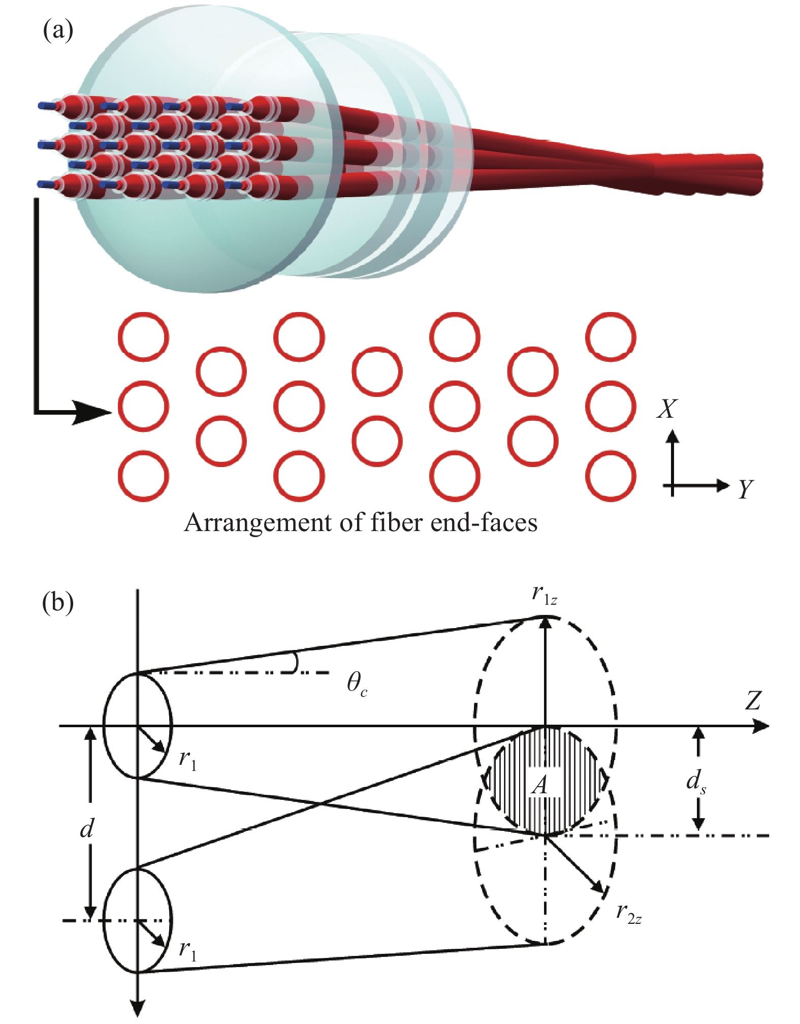
    Fig. 1. Schematic of laser incoherent space beam combining with a rectangular spot. (a) Changes in the space position of 18 laser beams; (b) Changes in the space position of two adjacent laser spots
    Variation between the beam propagation distance and the overlapping rate of the combined laser spot. (a) r=0, θc=10.0 mrad, different values of d; (b) θc=10.0 mrad, d=12 mm, different values of r; (c) r=3.5 mm, θc=14.8 mrad, d=12 mm
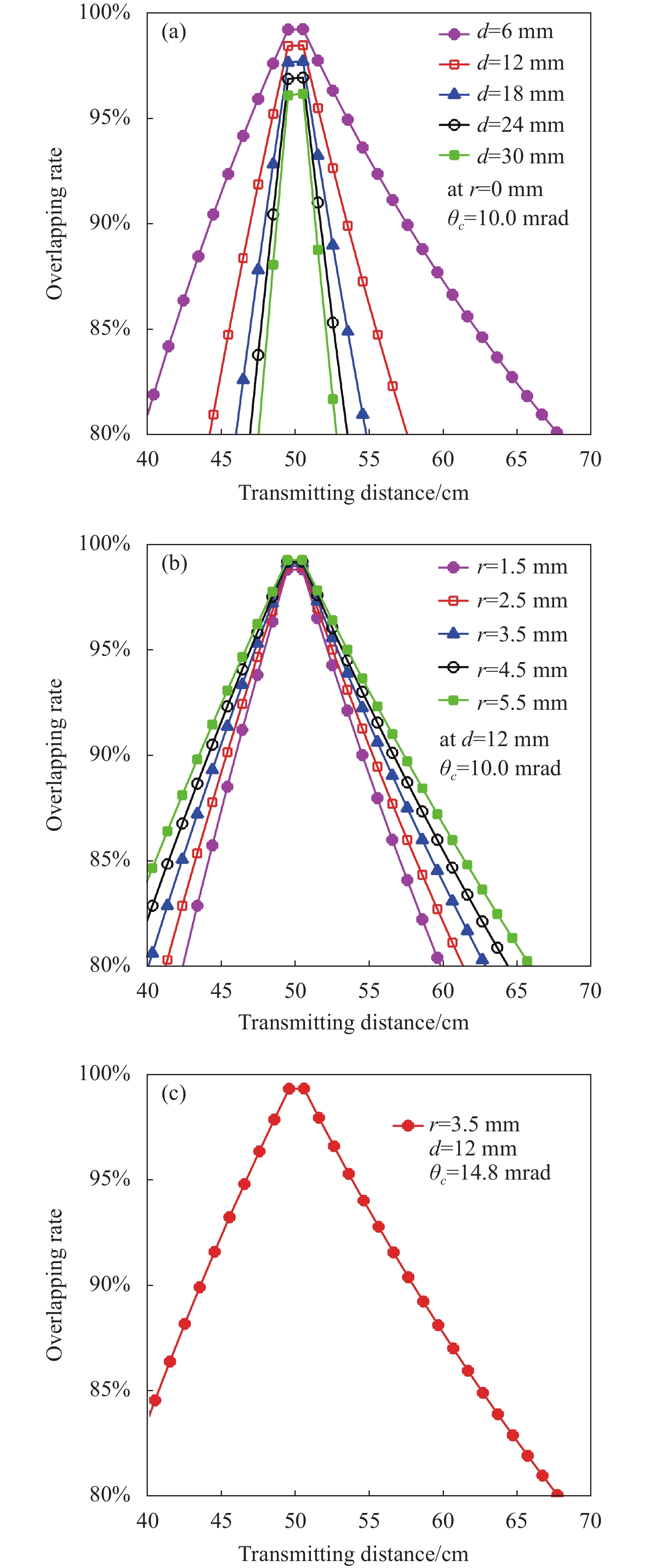
    Fig. 2. Variation between the beam propagation distance and the overlapping rate of the combined laser spot. (a) r=0, θc=10.0 mrad, different values of d; (b) θc=10.0 mrad, d=12 mm, different values of r; (c) r=3.5 mm, θc=14.8 mrad, d=12 mm
    Structural model of the beam combiner structure. (a) Collimation unit-XZ plane; (b) Combining unit-XZ plane; (c) Combining unit-YZ plane
    Fig. 3. Structural model of the beam combiner structure. (a) Collimation unit-XZ plane; (b) Combining unit-XZ plane; (c) Combining unit-YZ plane
    Spot energy simulation distribution of combined laser beam. (a) Δl=−150 mm; (b) Δl=−105 mm; (c) Δl=−100 mm; (d) Δl=−50 mm; (e) Δl=0 mm; (f) Δl=+50 mm; (g) Δl=+100 mm; (h) Δl=+105 mm; (i) Δl=+150 mm
    Fig. 4. Spot energy simulation distribution of combined laser beam. (a) Δl=−150 mm; (b) Δl=−105 mm; (c) Δl=−100 mm; (d) Δl=−50 mm; (e) Δl=0 mm; (f) Δl=+50 mm; (g) Δl=+100 mm; (h) Δl=+105 mm; (i) Δl=+150 mm
    Photos of 18×1 laser incoherent space beam combiner. (a) Engineering three-dimensional design drawing; (b) Engineering design drawing Y-Z axis section; (c) Photo of the fiber connection end face of the combiner; (d) Overall photo of the combiner
    Fig. 5. Photos of 18×1 laser incoherent space beam combiner. (a) Engineering three-dimensional design drawing; (b) Engineering design drawing Y-Z axis section; (c) Photo of the fiber connection end face of the combiner; (d) Overall photo of the combiner
    Hole morphology of the combined laser perforated steel plate sample along the combined beam direction. (a) Δl=−150 mm; (b) Δl=−105 mm; (c) Δl=−100 mm; (d) Δl=−50 mm; (e) Δl=0 mm; (f) Δl=+50 mm; (g) Δl=+100 mm; (h) Δl=+105 mm; (i) Δl=+150 mm
    Fig. 6. Hole morphology of the combined laser perforated steel plate sample along the combined beam direction. (a) Δl=−150 mm; (b) Δl=−105 mm; (c) Δl=−100 mm; (d) Δl=−50 mm; (e) Δl=0 mm; (f) Δl=+50 mm; (g) Δl=+100 mm; (h) Δl=+105 mm; (i) Δl=+150 mm
    Variation between the beam combining power and the pump current
    Fig. 7. Variation between the beam combining power and the pump current
    Laser spectrum before and after beam combination. (a) 18 laser beam independent spectrum superposition; Combined beam laser spectroscopy with (b) Δl=−100 mm; (c) Δl=−50 mm; (d) Δl=0 mm; (e) Δl=+50 mm; (f) Δl=+100 mm
    Fig. 8. Laser spectrum before and after beam combination. (a) 18 laser beam independent spectrum superposition; Combined beam laser spectroscopy with (b) Δl=−100 mm; (c) Δl=−50 mm; (d) Δl=0 mm; (e) Δl=+50 mm; (f) Δl=+100 mm
    NameSurface typeRadiusThicknessDiameter
    XY
    m1In: Sphere−72.1−72.12.07.0
    Out: Sphere+5.3+5.3
    m2In: Sphere+20.0+20.01.512.0
    Out: Sphere−11.8−11.8
    m3In: Sphere+30.0+30.03.612.0
    Out: Sphere+15.4+15.4
    M1In: Sphere+115.35+115.3526.0130.0
    Out: Sphere
    M2In: Sphere+114.02+114.0215.0110.0
    Out: Sphere+153.11+153.11
    M3In: Sphere−138.23−138.2310.0100.0
    Out: Sphere+78.40+78.40
    M4In: Cylinder+119.4810.090.0
    Out: Sphere
    M5In: Sphere3.090.0
    Out: Sphere
    Table 1. Parameters of the lenses (Unit: mm)
    ΔlSimulation valueMeasured valueEnergy distribution
    −15057.9×28.556.8×27.7Splitting
    −10550.1×22.649.0×21.4Splitting
    −10046.5×19.647.1×19.2Aggregation
    −5040.2×16.738.4×15.0Aggregation
    030.9×11.031.4×11.4Aggregation
    +5040.4×16.939.2×16.3Aggregation
    +10047.1×21.746.2×21.3Aggregation
    +10551.8×23.951.1×23.1Splitting
    +15058.5×29.158.1×28.5Splitting
    Table 2. Spot size of the combined beam laser (Unit: mm)
    Yi Wang, Guangzhi Lei, Lidong Yu, Rongwei Zha, Jingfeng Zhou, Yang Bai. High power laser incoherent spatial beam combining with rectangular spot[J]. Infrared and Laser Engineering, 2022, 51(4): 20210268
    Download Citation