
Chao Yin, Yanqiu Li, Xu Yan, Ke Liu, Lihui Liu. Tolerance Analysis of Micromirror Array in Deep Ultraviolet Lithography Illumination System[J]. Acta Optica Sinica, 2020, 40(7): 0722001
- Acta Optica Sinica
- Vol. 40, Issue 7, 0722001 (2020)
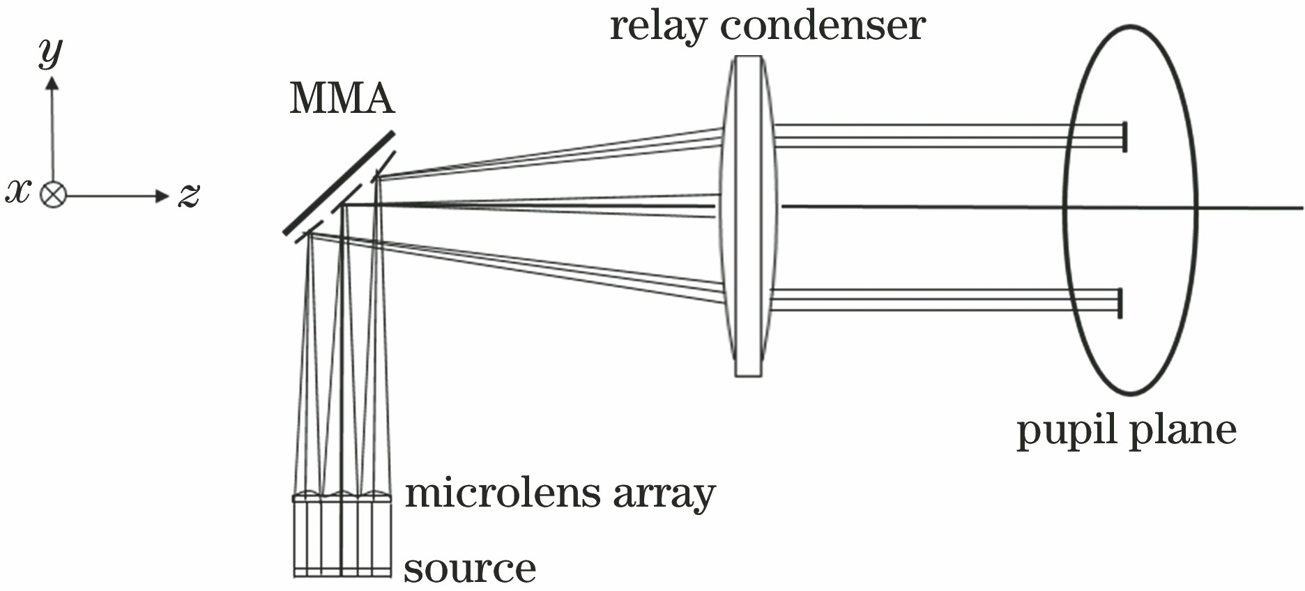
Fig. 1. Layout of beam shaping unit
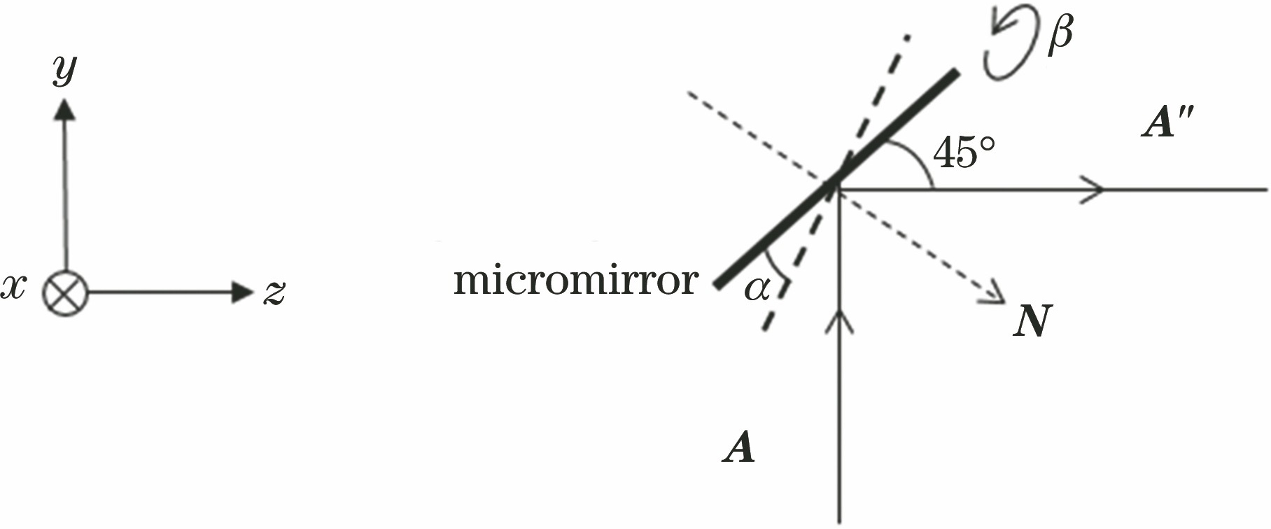
Fig. 2. Schematic of rotation angle characteristic and reflective light path of micromirror
Fig. 3. Flow chart of tolerance analysis of MMA
Fig. 4. Intensity distributions of illumination modes. (a) QI; (b) DI; (c) Zernike
Fig. 5. Exposure results of angle adjustment error for three kinds of illumination modes. (a) QI; (b) DI; (c) Zernike
Fig. 6. Exposure results of process angle error for three kinds of illumination modes. (a) QI; (b) DI; (c) Zernike
Fig. 7. Exposure results for different Δα and Δβ. (a) Angle adjustment error; (b) process angle error
Fig. 8. Cumulative probability distribution of ΔdCD under tolerance
|
Table 1. Main design specifications of MMA
|
Table 2. Main design specification of other elements
|
Table 3. Simulation results of angle of micromirror
|
Table 4. Exposure results of ideal illumination mode
|
Table 5. Exposure results of error illumination mode simulated by Matlab
|
Table 6. Exposure results of error illumination mode simulated by LightTools

Set citation alerts for the article
Please enter your email address
© Copyright 2018-2021 | Chinese Laser Press. All Rights Reserved 沪ICP备15018463号-20