
Fenxiang Wu, Jiabing Hu, Xingyan Liu, Zongxin Zhang, Peile Bai, Xinliang Wang, Yang Zhao, Xiaojun Yang, Yi Xu, Cheng Wang, Yuxin Leng, Ruxin Li, "Dispersion management for a 100 PW level laser using a mismatched-grating compressor," High Power Laser Sci. Eng. 10, 06000e38 (2022)
- High Power Laser Science and Engineering
- Vol. 10, Issue 6, 06000e38 (2022)
Abstract
1 Introduction
The development of high peak power lasers is of great significance in modern physics, as they can create extreme conditions and offer unprecedented means for high-field physical research. Due to the invention of chirped pulse amplification (CPA) and optical parametric chirped pulse amplification (OPCPA) techniques[1,2], several PW and 10 PW level lasers have been built worldwide, and the corresponding focused intensity has reached 1022–1023 W/cm2[3–10]. Moreover, some countries have also commissioned the construction of 100 PW level ultrahigh peak power lasers to pursue higher laser focused intensity and sequentially to explore frontier sciences, for example, the OPAL-75 PW in the USA, the XCELS-200 PW in Russia, the ELI-200 PW in Europe and the SEL-100 PW in China[11–14]. Currently, the majority of PW and 10 PW level lasers are based on the CPA technique with Ti:sapphire crystals. Nevertheless, limited by the available size of gain media and the transverse parasitic lasing[15], the Ti:sapphire-based CPA technique may not be a great choice for 100 PW level lasers. In contrast, benefiting from the achievable large size (>400 mm) and broad gain bandwidth (>200 nm) of deuterated potassium dihydrogen phosphate (DKDP) crystals, the DKDP-based OPCPA technique has been seriously considered as a promising approach for the development of 100 PW level lasers. Such ultrahigh peak power lasers are generally characterized by very large chirped pulse duration and an ultra-broad spectral bandwidth, in order to avoid the nonlinear effect in amplification and support sub-15 fs compressed pulses. Thus, one of the crucial tasks in such 100 PW level lasers is the dispersion control, which determines the temporal profile as well as the peak power of laser pulses.
The dispersion matching among the stretcher, amplifiers and compressor in different orders is known to be vital for minimizing the pulse duration. However, the two degrees of the freedom in traditional Treacy compressors, that is, the incident angle and the grating pair separation, can only control the second- and third-order dispersions (GDD, TOD). The residual high-order dispersion, especially the fourth-order dispersion (FOD), is still a bottleneck to achieve near-Fourier transform limit (FTL) pulse compression. In order to control the FOD, several dispersion compensation methods have been developed, for example, the mechanically deformable mirror[16], liquid-crystal modulator[17], grism pair[18], acousto-optic programmable dispersive filter (AOPDF)[19] and negative and positive chirped pulse amplification (NPCPA) scheme[20]. Limited by the dynamic range and spectral resolution, the deformable mirror and liquid-crystal modulator are seldom applied in high peak power lasers. The AOPDF and grism pair have been successfully applied in several high peak power lasers[18,21,22], but their low transmission efficiency will affect subsequent amplification and finally degrade the pulse temporal contrast[23], which is a fatal parameter for 100 PW level lasers. Besides, the angular dispersion introduced by the AOPDF is also a problem that should be carefully treated. Although the NPCPA scheme has the potential to completely compensate the FOD without using any additional dispersion compensation components, it is only numerically demonstrated up to multi-PW lasers. Recently, another dispersion control method based on the combination of a double-grating Offner stretcher and a Treacy compressor has been proposed and demonstrated in PW level OPCPA systems[24]. However, this method may be invalid for 100 PW level lasers because of the significant increase of the material dispersion.
The mismatched-grating compressor was first proposed in 1997 by Kane and Squier[25]. Different from the conventional Treacy compressor, an extra variable parameter (the grating groove density) is introduced by the mismatched-grating compressor. In this scheme, GDD and TOD can be exactly compensated by mismatching the grating pair separation and the incident angle in the stretcher and compressor, respectively. Simultaneously, FOD can be nearly cancelled out by mismatching the grating groove density in the stretcher and compressor. In this scheme, the gratings in the compressors generally possess a higher grating groove density than those in the stretchers. Because GDD, TOD and FOD can be simultaneously compensated, near-FTL compressed pulses should be available by using a mismatched-grating compressor in theory. However, the previous experimental results in two PW level femtosecond lasers based on the mismatched-grating compressor were not favorable. The compressed pulse durations barely reached approximately 30 fs, which is far from the FTL value[26,27]. This is mainly because the gratings adopted in the above two lasers were not equipped with the optimal groove density, which was limited by the commercially available gratings of that time. Fortunately, with the development of grating manufacturing techniques, gratings with arbitrary groove density are customizable nowadays[28–30], which makes the mismatched-grating compressor possess the potential for good dispersion management. However, the feasibility of the mismatched-grating compressor in practical applications is still uncertain. As a kind of passive dispersion management method, the optimal grating groove density has to be predetermined according to the calculated dispersion in lasers. Once there is a dispersion deviation in a stretcher or material, the validity of the mismatched-grating compressor has to be reevaluated. On the other hand, the error of the desired grating groove density should also be taken into consideration. That is to say, the tolerance analysis is crucially important for the practical application of the mismatched-grating compressor. However, there are few reports on the tolerances of the mismatched-grating compressor so far to the best of our knowledge.
Sign up for High Power Laser Science and Engineering TOC. Get the latest issue of High Power Laser Science and Engineering delivered right to you!Sign up now
In this work, we focus on the dispersion control in 100 PW level lasers based on the mismatched-grating compressor. The numerical results show that near-FTL compressed pulses with 12.8 fs duration can be realized in the mismatched-grating compressor based SEL-100 PW laser facility, which has a chirped pulse duration of 4 ns and a spectral bandwidth of 210 nm. Furthermore, we also investigate the tolerances of a mismatched-grating compressor scheme for the dispersion control in this 100 PW level laser, including the tolerance to the incident angle and the grating pair separation in the stretcher, the grating groove density in the stretcher and the material dispersion in the laser system. The numerical results effectively clarify that good tolerances and near-FTL pulse durations can be achieved simultaneously by keeping a balance among the residual GDD, TOD and FOD in the laser system. The good tolerances of the mismatched-grating compressor are necessary and crucially important for its practical application. Hence, this work provides a meaningful guideline for the design and construction of 100 PW level lasers.
2 Design of the SEL-100 PW laser based on the mismatched-grating compressor
The SEL-100 PW laser facility was started in 2018[14], aiming at investigations of strong field quantum electrodynamics, vacuum birefringence and positron–electron pair generation from vacuum[31–33], based on collisions with intense hard X-ray lasers. As shown in Figure 1, the SEL-100 PW laser facility mainly consists of a high-contrast laser seed source, a double-grating Offner stretcher, three lithium triborate (LBO)-based OPCPA power amplifiers, two DKDP-based OPCPA high-energy main amplifiers and a Treacy compressor. The real aberration-free characteristic endows the double-grating Offner stretcher with the advantages of good beam quality and a perfect dispersion match with a conjugated Treacy compressor[24]. The OPCPA amplifiers above feature very broad gain bandwidth, and the amplified output spectrum is able to support sub-15 fs pulse duration. In addition, to avoid pulse front distortion caused by chromatic aberration in the lenses[34–36], all the telescopes are designed as reflective-type utilizing off-axis parabolic (OAP) mirrors, which also can decrease the lens-introduced material dispersion in this 100 PW level laser facility.
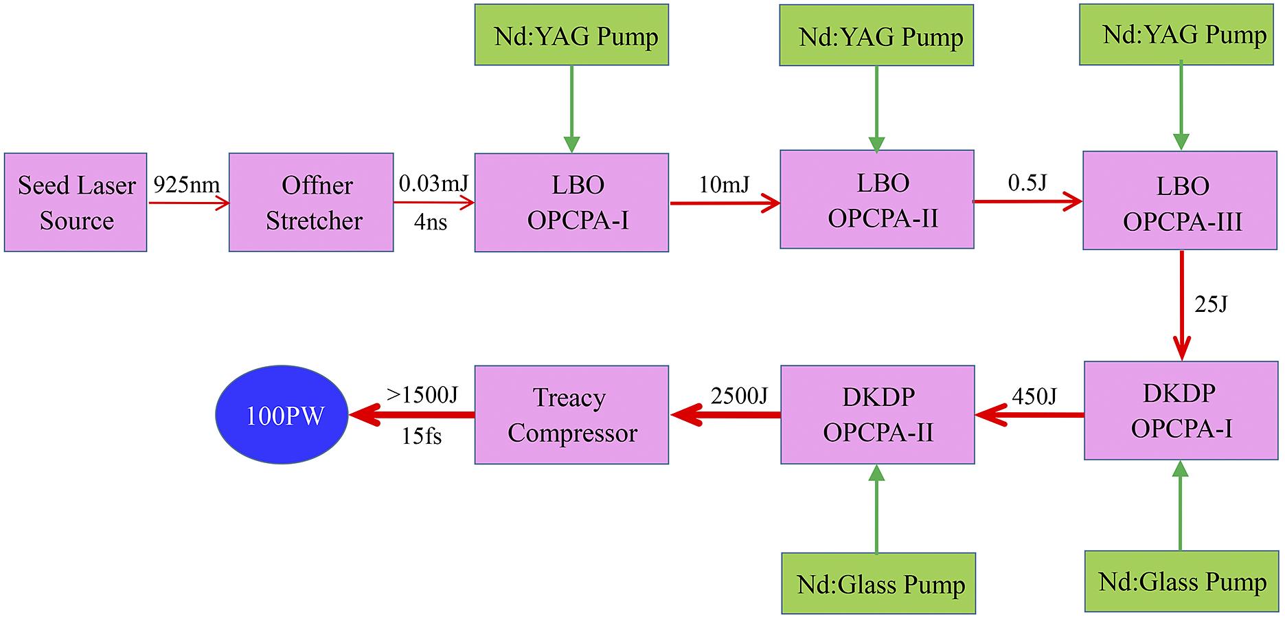
Figure 1.The schematic of our scheduled SEL-100 PW laser facility.
The seed laser source has been developed[37], which includes a commercial Ti:sapphire kHz femtosecond laser, an infrared OPA, a gas-filled hollow core fiber and a cascaded second harmonic generation module. The output spectral width is approximately 265 nm with a central wavelength of 925 nm, the pulse energy is approximately 100 μJ, the pulse duration is approximately 10 fs (very close to the FTL value) and the temporal contrast is about the 10–11 level. The seed pulses are firstly injected into a double-grating Offner stretcher for temporal broadening. After the stretcher, the pulse spectrum ranges from 820 to 1030 nm, with a width of 210 nm and a chirped duration of 4 ns. The chirped pulses are firstly amplified to 25 J by the three LBO-based OPCPA power amplifiers, then further amplified to 2500 J by the two DKDP-based OPCPA high-energy main amplifiers and finally temporally compressed to sub-15 fs by the Treacy compressor. Consequently, laser pulses with more than 1500 J energy and sub-15 fs duration are promising to achieve, which corresponds to a peak power exceeding 100 PW.
Based on a comprehensive consideration of the beam size, spectral bandwidth, dispersion ability and diffraction efficiency, the Treacy compressor is designed based on four meter-scale golden gratings with a groove density of 1400 g/mm from Horiba Jobin Yvon[29]. The incident angle and the grating pair separation of this Treacy compressor are 61° and 1200 mm, respectively, with a compression factor of –19.9 ps/nm. The material dispersion is introduced by the nonlinear crystals (LBO and DKDP) and fused silica is used for dichroic mirrors and window plates in the laser facility, with total thicknesses of 72 mm (LBO), 79 mm (DKDP) and 1130 mm (fused silica). In addition to material dispersion, the optical parameter phase (OPP)[38] in all OPCPA amplifiers is also considered. The double-grating Offner stretcher will also employ golden gratings, and finally be designed based on the dispersion parameters of the above Treacy compressor, materials and OPP. As the required grating size in the stretcher is generally much smaller than that in the compressor, the gratings in the stretcher are much cheaper and easier to handle.
In this work, the stretcher and compressor are analyzed by the ray-tracing method[39], the material dispersion is calculated by the Sellmeier formula[40] and the OPP is simulated by the coupled-wave equation[38,41]. This calculation model is based on MATLAB, and has been demonstrated in our previous works[24,37]. The phases of a double-grating Offner stretcher and a Treacy compressor are as shown in Equations (1) and (2), respectively. Here, ω is the angular frequency of pulses, G is the perpendicular separation of the grating pair, d is the groove density of the grating, θ and β are the incident and diffraction angles of the pulses, respectively, and the second term 2πGd–1(tan β) is the so-called phase correction term. The dispersion (GDD, TOD, FOD) is found by the according derivate of the phase with respect to ω:
Normally, the stretcher will also be designed with 1400 g/mm gratings, which match that in the compressor. However, the residual FOD in this case will reach up to approximately 5.5 × 10⁵ fs4, when the GDD and TOD are simultaneously cancelled out by optimizing the incident angle and the grating pair separation in the compressor. Such a large amount of residual FOD is difficult to be compensated unless some extra dispersion compensation methods are adopted, and hence it will significantly lengthen the pulse duration and degrade the temporal profile of the compressed pulses.
In order to directly achieve dispersion control over the GDD, TOD and FOD simultaneously, a mismatched-grating compressor scheme is implemented in this 100 PW laser facility. Based on the numerical analysis, the optimal grating groove density for the stretcher is 1364 g/mm, which does not match that in the above compressor. In this stretcher, the incident angle and the grating pair separation are 56.04° and 618.1 mm, respectively, and the curvature radii of the concave and the convex mirrors are 2 and 1 m, respectively. As a result, the chirped factor of this stretcher is about 19.8 ps/nm, corresponding to a chirped pulse duration of around 4 ns. Given the above, the residual dispersions of the mismatched-grating compressor based SEL-100 PW laser facility are about 1 fs2, –5 fs3 and –5895 fs4, respectively. The detailed dispersion parameters of the double-grating Offner stretcher, the amplifiers and the Treacy compressor are listed in Table 1.
| GDD/fs2 | TOD/fs3 | FOD/fs4 | |
|---|---|---|---|
| Stretcher | 8,756,341 | –21,501,508 | 85,574,250 |
| Material | 32,715 | 45,541 | –41,130 |
| OPP | 426 | –3698 | –23,620 |
| Compressor | –8,789,481 | 21,459,660 | –85,515,395 |
| Residual | 1 | –5 | –5895 |
Table 1. Dispersion at the 925 nm central wavelength of the SEL-100 PW laser facility.
A 10th-order super-Gaussian laser spectrum ranging from 820 to 1030 nm is simulated and shown in Figure 2(a), which can support an FTL pulse duration of 12.6 fs. The temporal profile and the spectral phase of the compressed pulses are also calculated based on the design above, as shown in Figure 2. The phase distortion occurs mainly at the edge of the whole spectrum, and the maximal distortion is better than –1 rad. In this situation, the phase distortion-induced influence on pulse compression is slight and ignorable. The temporal duration of compressed pulses is about 12.8 fs, which is very close to the FTL. This pulse duration is shorter than the expected value of sub-15 fs, and hence a higher laser peak power is promising based on the design above.
![]()
Figure 2.(a) Simulated pulse spectrum and calculated spectral phase. (b) FTL and corresponding compressed pulses of the SEL-100 PW laser facility.
The numerical results indicate that special mismatching between the grating groove density in the stretcher and compressor is feasible to realize dispersion management for a 100 PW level laser featuring an ultra-broadband spectrum and large chirped pulse duration. In addition, it is notable that the mismatched-grating compressor scheme is realized by optimizing the grating groove density in the stretcher here, in consideration of the required grating size in the stretcher usually being much smaller than that in compressor. This scheme can also be achieved by directly optimizing the grating groove density in the compressor.
3 Tolerance analysis
Although our simulated result shows that the mismatched-grating compressor scheme can facilitate the static dispersion compensation as high as the FOD in theory, the practical performance will be greatly limited by the application conditions. As this scheme is fully based on the estimation of the dispersion in the laser system, the feasibility is still doubtful once there is an error between the estimated and the actually induced dispersion values. In other words, the tolerances of such a passive dispersion management scheme based on the mismatched-grating compressor are crucially important and necessary. In order to further demonstrate the feasibility of the mismatched-grating compressor for the dispersion control in the SEL-100 PW laser, the numerical investigation of its tolerances will be implemented in the following sections, including tolerance to the misalignment of the stretcher, error of the desired grating groove density in the stretcher and variation of the material dispersion in the laser system.
3.1 Tolerance to misalignment of the stretcher
In the design above, the incident angle and the grating pair separation in the 1364 g/mm grating based stretcher are 56.04° and 618.1 mm, respectively. Assuming that the incident angle or the grating pair separation in the stretcher deviates from the preset parameters due to misalignment, then the feasibility of mismatched-grating compressor, that is, its tolerance to the misalignment of the stretcher, should be carefully investigated.
In order to investigate the tolerance of the mismatched-grating compressor to the misalignment of the stretcher, the residual FOD and the corresponding compressed pulse duration are calculated, as there is a variation of the incident angle or the grating pair separation in the stretcher. In the calculations, the GDD and TOD are simultaneously cancelled out by adjusting the compressor. The numerical results show that a sub-15 fs compressed pulse duration is always available in the case of an incident angle deviation between –3.8° and 2.3° or a grating pair separation deviation from –20 to 17 mm, shown as the pink bars in Figures 3(a) and 4(a).
![]()
Figure 3.(a) The residual FOD and corresponding pulse duration with the change of incident angle in the stretcher when the GDD and TOD are cancelled out. (b) The pulse duration after balancing the GDD, TOD and FOD by optimizing the compressor, when the incident angle deviation in the stretcher is +4°.
![]()
Figure 4.(a) The residual FOD and corresponding pulse duration with the change of the grating pair separation in the stretcher when the GDD and TOD are cancelled out. (b) The pulse duration after balancing the GDD, TOD and FOD by optimizing the compressor, when the grating pair separation deviation in the stretcher is +20 mm.
As the deviation of incident angle continues to increase, such as to 4°, the residual FOD will reach –30,917 fs4. Such a residual FOD can lengthen the compressed pulse duration to approximately 18.4 fs. However, this result is obtained by simultaneous cancellation of the GDD and TOD. If a balance among the residual GDD, TOD and FOD can be achieved, the pulse duration has the potential to be further shortened[42] and, hence, the tolerance of the mismatched-grating compressor will be better. For this purpose, the 1400 g/mm gratings-based compressor is optimized with an incident angle of 65.75° and a grating pair separation of 1220.1 mm, corresponding to residual dispersions of 120 fs2, 665 fs3 and –36,728 fs4. As a result, the pulse duration is reduced from approximately 18.4 fs to approximately 12.9 fs. The spectral phase and temporal profile of the compressed pulses under this condition are shown in Figure 3(b). Similarly, the tolerance to the deviation of the grating pair separation in the stretcher can also be improved by keeping a balance between the residual dispersions. For example, when the deviation of grating pair separation increases to 20 mm, the residual FOD will reach up to –23,783 fs4 as the GDD and TOD are eliminated simultaneously, corresponding to a compressed pulse duration of approximately 15.8 fs, shown as the dashed circle in Figure 4(a). For this condition, the incident angle and the grating pair separation in the compressor can be optimized to 60.98° and 1238.4 mm, respectively. Then, the residual dispersions are about 110 fs2, 568 fs3 and –29,077 fs4, resulting in a compressed pulse duration of approximately 12.7 fs. The spectral phase and temporal profile of the compressed pulses in this case are shown in Figure 4(b).
The numerical results above demonstrate a very high tolerance of the mismatched-grating compressor to the misalignment (incident angle or grating pair separation) of the stretcher. In particular, we can find that a better tolerance can be achieved by making a balance among the residual dispersion rather than eliminating the GDD and TOD simultaneously. Thereby, the tolerance of stretcher misalignment (incident angle and grating pair separation simultaneously) is not investigated in detail, but a poor alignment case is analyzed as an example.
When the deviations of the incident angle and grating pair separation in the stretcher are 4° and 20 mm simultaneously, this should be a very poor alignment situation. However, the laser pulses still can be compressed to approximately 13.7 fs in this case by optimizing the compressor to an incident angle of 65.73° and a grating pair separation of 1259.2 mm. The residual dispersions are about 163 fs2, 694 fs3 and –54,300 fs4. In other words, the mismatched-grating compressor scheme also has a high tolerance to simultaneous misalignments of the incident angle and grating pair separation in the stretcher.
3.2 Tolerance to the grating groove density in stretcher
Based on the analysis in Section 2, the optimal design of the stretcher is based on 1364 g/mm gratings, which can cancel out the GDD and TOD, while keeping a small amount of the residual FOD. To investigate the tolerance of the mismatched-grating compressor to the desired grating groove density, the compressed pulse duration with the variation of the grating groove density in the stretcher is numerically analyzed by making a balance among the residual dispersions. As Figure 5(a) shows, the pulse duration below 13.9 fs (1.1FTL) is always available with the grating groove density between 1361 and 1368 g/mm (shown as the pink bar), and the pulse duration below 15.1 fs (1.2FTL) can be obtained within a larger range from 1360 to 1369 g/mm (shown as the purple bar).
![]()
Figure 5.(a) The compressed pulse duration with the change of the grating groove density in the stretcher, after balancing the residual dispersion. (b) The residual FOD and corresponding pulse duration with the change of the grating groove density in the stretcher when the GDD and TOD are cancelled out.
To make a comparison, the numerical results based on the simultaneous cancellation of the GDD and TOD are also presented, as shown in Figure 5(b). We can find that the amount of residual FOD and the corresponding pulse duration will increase significantly, just with a slight deviation of the grating groove density from the optimal value. A sub-15 fs pulse duration can be achieved only in the cases of 1363, 1364 and 1365 g/mm. This result demonstrates, once again, that a better tolerance can be realized by keeping a balance among the residual dispersions compared with eliminating the GDD and TOD simultaneously. For simplicity, in the following numerical analysis, the dispersion management scheme is only investigated based on a balance among the residual GDD, TOD and FOD.
To reveal more details of the analysis above, two specific examples are presented below. In the first case, the stretcher is composed of two 1361 g/mm gratings, and the 1400 g/mm gratings-based compressor is optimized with an incident angle of 61.41° and a grating pair separation of 1197.4 mm. As a result, the residual dispersions in the laser system are about 190 fs2, 1070 fs3 and –61,317 fs4, respectively, corresponding to a compressed pulse duration of approximately 13.5 fs (<1.1FTL). The spectral phase and pulse duration of the compressed pulses are shown in Figure 6(a). In the second case, the grating groove density in the stretcher is 1369 g/mm and the incident angle and the grating pair separation of the compressor are optimized accordingly to 60.33° and 1204.0 mm, resulting in residual dispersions of –227 fs2, –1011 fs3 and 81,924 fs4, respectively. As a result, compressed pulses with approximately 15.0 fs duration (<1.2FTL) are obtained, as shown in Figure 6(b).
![]()
Figure 6.The pulse durations after balancing the residual dispersion by optimizing the compressors when the grating groove densities in the stretchers are (a) 1361 g/mm and (b) 1369 g/mm.
According to the above numerical investigation, we can know that the available grating groove densities for the stretcher are between 1360 and 1369 g/mm. This result demonstrates a good tolerance of the mismatched-grating compressor to the grating groove density in the stretcher, in terms of contemporary grating manufacturing technology.
3.3 Tolerance to the material dispersion in laser system
Generally, there is always an error between the actual introduced and the estimated material dispersion in a laser system. Thus, it should also be quite important and meaningful to investigate the tolerance of the mismatched-grating compressor to the variation of material dispersion, for its practical application.
In the design of the SEL-100 PW laser facility in Section 2, the material dispersion induced by the nonlinear crystals (LBO and DKDP) should be much lower than that introduced by the dichroic mirrors and window plates, which are all made of fused silica and have a total thickness around 1130 mm. Thus, we just consider the variation of fused silica-induced material dispersion in the following numerical investigations. The compressed pulse duration variation versus fused silica thickness is numerically calculated and shown in Figure 7. The results show that a pulse duration below 13.9 fs (1.1FTL) can be achieved when the fused silica thickness error is between –110 and 135 mm, shown as the pink bar in Figure 7 . Besides, the pulse duration below 15.1 fs (1.2FTL) is still available when the error varies from –150 to 180 mm, shown as the purple bar in Figure 7. As a result, it indicates a good tolerance to the material dispersion in the laser system for the mismatched-grating compressor. The good tolerance will make this scheme feasible in practical applications.
![]()
Figure 7.The calculated pulse durations with the variation of fused silica thickness in the laser system, after balancing the residual GDD, TOD and FOD by optimizing the compressor.
Two special examples are presented again to reveal more details of above numerical analysis. In the first example, the error of fused silica thickness is supposed to be –150 mm. Meanwhile, the incident angle and grating pair separation in the 1400 g/mm gratings-based compressor are 60.93° and 1198.4 mm, respectively, corresponding to residual dispersions of 235 fs2, 1004 fs3 and –84,561 fs4. As a result, a pulse duration of approximately 15.0 fs can be obtained. The spectral phase and temporal profile of the compressed pulse are shown in Figure 8(a). In the second example with a fused silica thickness error of 120 mm, when the incident angle and the grating pair separation in the compressor are optimized to 61.05° and 1201.2 mm, respectively, residual dispersions of about –180 fs2, –1150 fs3 and 57,114 fs4 are achieved. Then, a compressed pulse duration of approximately 13.3 fs can be realized, as shown in Figure 8(b).
![]()
Figure 8.The pulse durations after balancing the residual dispersion by optimizing the compressor when the fused silica thickness errors in the laser system are (a) –150 mm and (b) 120 mm.
3.4 Simultaneous tolerance to the grating groove density and material dispersion
Based on Sections 3.2 and 3.3, the tolerance of the mismatched-grating compressor to the simultaneous deviations of the grating groove density in the stretcher and the material dispersion in the laser is also investigated. Figure 9(a) shows the compressed pulse duration variation after balancing the residual dispersion, where the blue and pink shades correspond to 1.1FTL and 1.2FTL, respectively. We can see that compressed pulses below 1.2FTL can be achieved in a relatively large region.
![]()
Figure 9.The pulse durations (a) and their partial projection (b) after balancing the residual dispersion by optimizing the compressor when the grating groove density in the stretcher and the material dispersion in the laser system are changing simultaneously.
To see the results more clearly, the projection of the available region (<1.2FTL) on the horizontal plane is shown in Figure 9(b). With the increase of grating groove density, the tolerable range of fused silica thickness error changes in one direction, and with a similar range length. For example, when the grating groove density in the stretcher is 1361 g/mm, the tolerance range of the fused silica thickness error is from about –40 to 270 mm. When the grating groove density in the stretcher increases to 1368 g/mm, the corresponding tolerance range of the fused silica thickness error varies from about –260 to 50 mm. Their range lengths are around 310 mm. While viewed from another perspective, the tolerable range of grating groove density will decrease with the increase of fused silica thickness error. In the case of no material dispersion error, the available range of grating groove density is largest, from 1360 to 1369 g/mm. When the fused silica thickness error increases to ±140 mm, the tolerable ranges of grating groove density are changed to be 1359–1365 and 1364–1370 g/mm, respectively. Therefore, the grating groove density and material dispersion are mutually related and restricted. After making a compromise between the deviations of grating groove density and material dispersion, relatively proper tolerable ranges (1362–1367 g/mm and from 70 to –70 mm) are achieved, shown as the red area in Figure 9(b). Within this area, sub-15 fs compressed pulses always can be achieved. Hence, we can find that the mismatched-grating compressor also has enough tolerance even when the grating groove density in the stretcher and the material dispersion in the laser simultaneously change.
In short, the mismatched-grating compressor based dispersion management scheme is highly tolerant to the misalignment of the stretcher, including its incident angle and grating pair separation. Moreover, this scheme is also tolerant enough to the grating groove density in the stretcher as well as the material dispersion in the laser system. Thus, the mismatched-grating compressor should be practical for dispersion management in 100 PW level lasers.
4 Conclusion
In summary, the dispersion management for a 100 PW level laser by using a mismatched-grating compressor is numerically demonstrated. This scheme can make it possible to simultaneously cancel out the GDD, TOD and FOD, without utilizing any extra dispersion compensation methods. The numerical results show that near-FTL pulses can be achieved in the mismatched-grating compressor based SEL-100 PW laser facility, featuring 4 ns chirped pulse duration and 210 nm spectral bandwidth. More importantly, we also thoroughly investigate the tolerances of the mismatched-grating compressor scheme, including the tolerance to misalignment of the stretcher, error of the desired grating groove density in the stretcher and variation of the material dispersion in the laser system. The results efficiently demonstrate that good tolerances and near-FTL compressed pulses can be obtained simultaneously by keeping a balance among the residual dispersions, which is a further proof of the feasibility of the practical application of the mismatched-grating compressor. Hence, the mismatched-grating compressor should be a feasible and promising scheme for the dispersion management of 100 PW level lasers. This scheme can also be backwards compatible to PW as well as 10 PW level lasers.
Declaration of competing interests
The authors declare that they have no known competing financial interests or personal relationships that could have appeared to influence the work reported in this paper.
References
[1] D. Strickland, G. Mourou. Opt. Commun., 55, 219(1985).
[2] D. G. Jonušauskas, A. Piskarskas. Opt. Commun., 88, 437(1992).
[3] H. Kiriyama, A. S. Pirozhkov, M. Nishiuchi, Y. Fukuda, K. Ogura, A. Sagisaka, Y. Miyasaka, M. Mori, H. Sakaki, N. P. Dover, K. Kondo, J. K. Koga, T. Z. Esirkepov, M. Kando, K. Kondo. Opt. Lett., 43, 2595(2018).
[4] Z. Zhang, F. Wu, J. Hu, X. Yang, J. Gui, X. Liu, C. Wang, Y. Liu, X. Lu, Y. Xu, Y. Leng, R. Li, Z. Xu. High Power Laser Sci. Eng., 8, e4(2020).
[5] H. Kiriyama, Y. Miyasak, A. Kon, M. Nishiuchi, A. Sagisaka, H. Sasao, A. S. Pirozhkov, Y. Fukuda, K. Ogura, K. Kondo, N. P. Dover, M. Kando. High Power Laser Sci. Eng., 9, e62(2021).
[6] J. H. Sung, H. W. Lee, J. Y. Yoo, J. W. Yoon, C. W. Lee, J. M. Yang, Y. J. Son, Y. H. Jang, S. K. Lee, C. H. Nam. Opt. Lett., 42, 2058(2017).
[7] X. Zeng, K. Zhou, Y. Zuo, Q. Zhu, J. Su, X. Wang, X. Wang, X. Huang, X. Jiang, D. Jiang, Y. Guo, N. Xie, S. Zhou, Z. Wu, J. Mu, H. Peng, F. Jing. Opt. Lett., 42, 2014(2017).
[8] J. W. Yoon, C. Jeon, J. Shin, S. K. Lee, H. W. Lee, I. W. Choi, H. T. Kim, J. H. Sung, C. H. Nam. Opt. Express, 27, 20412(2019).
[9] F. Lureau, G. Matras, O. Chalus, C. Derycke, T. Morbieu, C. Radier, O. Casagrande, S. Laux, S. Ricaud, G. Rey, A. Pellegrina, C. Richard, L. Boudjemaa, C. S. Boisson, A. Baleanu, R. Banici, A. Gradinariu, C. Caldararu, B. D. Boisdeffre, P. Ghenuche, A. Naziru, G. Kolliopoulos, L. Neagu, R. Dabu, I. Dancus, D. Ursescu. High Power Laser Sci. Eng., 8, e43(2020).
[10] J. W. Yoon, Y. G. Kim, I. W. Choi, J. H. Sung, H. W. Lee, S. K. Lee, C. H. Nam. Optica, 8, 630(2021).
[11] J. D. Zuegel, S.W. Bahk, I. A. Begishev, J. Bromage, C. Dorrer, A. V. Okishev, J. B. Oliver: Applications & Technology. , , , , , , and , in 2014, (), paper JTh4L-4.(2014).
[12] A. Shaykin, I. Kostyukov, A. Sergeev, E. Khazanov. Reza Kenkyu, 42, 141(2014).
[13] E. Cartlidge. Science, 355, 785(2017).
[14] Y. Peng, Y. Xu, L. Yu, X. Wang, Y. Li, X. Lu, C. Wang, J. Liu, C. Zhao, Y. Liu, C. Wang, X. Liang, Y. Leng, R. Li. Rev. Laser Eng., 49, 93(2020).
[15] S. Laux, F. Lureau, C. Radier, O. Chalus, F. Caradec, O. Casagrande, E. Pourtal, C. Simon-Boisson, F. Soyer, P. Lebarny. Opt. Lett., 37, 1913(2012).
[16] E. Zeek, K. Maginnis, S. Backus, U. Russek, M. Murnane, G. Mourou, H. Kapteyn, G. Vdovin. Opt. Lett., 24, 493(1999).
[17] A. M. Weiner, D. E. Leaird, J. S. Patel, J. R. Wullert. IEEE J. Quantum Electron., 28, 908(1992).
[18] S. Li, C. Wang, Y. Liu, Y. Xu, Y. Li, X. Liu, Z. Gan, L. Yu, X. Liang, Y. Leng, R. Li. Opt. Express, 25, 17488(2017).
[19] V. Laude, Z. Cheng, C. Spielmann, P. Tournois. Opt. Lett., 25, 575(2000).
[20] F. Wu, C. Wang, J. Hu, Z. Zhang, X. Yang, X. Liu, Y. Liu, P. Ji, P. Bai, J. Qian, J. Gui, Y. Xu, Y. Leng. Opt. Express, 28, 31743(2020).
[21] M. Galletti, P. Oliveira, M. Galimberti, M. Ahmad, G. Archipovaite, N. Booth, E. Dilworth, A. Frackiewicz, T. Winstone, I. Musgrave, C. H. Gomez. High Power Laser Sci. Eng., 8, e31(2020).
[22] J. Bromage, S.-W. Bahk, M. Bedzyk, I. A. Begishev, S. Bucht, C. Dorrer, C. Feng, C. Jeon, C. Mileham, R. G. Roides, K. Shaughnessy, M. J. Shoup, M. Spilatro, B. Webb, D. Weiner, J. D. Zuegel. High Power Laser Sci. Eng., 9, e63(2021).
[23] Y. Xu, Y. Huang, Y. Li, J. Wang, X. Lu, Y. Leng, R. Li, Z. Xu. IEEE J. Quantum Electron., 48, 516(2012).
[24] F. Wu, X. Liu, X. Wang, J. Hu, X. Lu, Y. Li, Y. Peng, Y. Liu, J. Chen, Y. Long, W. Li, Z. Zhang, Y. Xu, C. Wang, Y. Leng, R. Li. Opt. Laser Tech., 148, 107791(2022).
[25] S. Kane, J. Squier. J. Opt. Soc. Am. B, 14, 1237(1997).
[26] M. Aoyama, K. Yamakawa, Y. Akahane, J. Ma, N. Inoue, H. Ueda, H. Kiriyama. Opt. Lett., 28, 1594(2003).
[27] X. Liang, Y. Leng, C. Wang, C. Li, L. Lin, B. Zhao, Y. Jiang, X. Lu, M. Hu, C. Zhang, H. Lu, D. Yin, Y. Jiang, X. Lu, H. Wei, J. Zhu, R. Li, Z. Xu. Opt. Express, 15, 15335(2007).
[28] D. Kramer, J. Novák, B. Rus. EPJ Web Conf., 48, 00010(2013).
[30] https://www.plymouthgrating.com. https://www.plymouthgrating.com
[31] Y. Wu, L. Ji, R. Li. Photon. Res., 9, 541(2021).
[32] N. Ahmadiniaz, M. Bussmann, A. Debus, T. Kluge, R. Schuetzhold. Phys. Rev. D, 104, L011902(2021).
[33] O. Olugh, Z. Li, B. Xie. High Power Laser Sci. Eng., 8, e38(2020).
[34] Z. Bor. J. Mod. Opt., 35, 1907(1988).
[35] F. Wu, Z. Zhang, X. Yang, J. Hu, Y. Xu, Y. Leng. Appl. Sci., 10, 8586(2020).
[36] L. Li, Q. Yuan, R. Chen, X. Zou, W. Zang, T. Li, G. Zheng, S. Wang, Z. Wang, S. Zhu. Chin. Opt. Lett., 18, 082401(2020).
[37] X. Wang, X. Liu, X. Lu, J. Chen, Y. Long, W Li, H. Chen, X. Chen, P. Bai, Y. Li, Y. Peng, Y. Liu, F. Wu, C. Wang, Z. Li, Y. Xu, X. Liang, Y. Leng, R. Li. Ultrafast Sci, 2022(2022).
[38] B. Zhou, J. Ma, J. Wang, D. Tang, G. Xie, P. Yuan, H. Zhu, L. Qian. Phys. Rev. A, 95, 033841(2017).
[39] J. Jiang, Z. G. Zhang, T. Hasama. J. Opt. Soc. Am. B, 19, 678(2002).
[40] D. N. Nikogosyan. Nonlinear Optical Crystals: A Complete Survey(2005).
[41] S. Witte, K. S. E. Eikema. IEEE J. Quantum Electron., 18, 296(2012).
[42] V. Bagnoud, F. Salin. IEEE J. Sel. Top. Quant. Electron., 4, 445(1998).


Set citation alerts for the article
Please enter your email address

© Copyright 2018-2021 | Chinese Laser Press. All Rights Reserved 沪ICP备15018463号-20