
Wanvisa Talataisong, Jon Gorecki, Lieke D. van Putten, Rand Ismaeel, James Williamson, Katie Addinall, Daniel Schwendemann, Martynas Beresna, Vasilis Apostolopoulos, Gilberto Brambilla. Hollow-core antiresonant terahertz fiber-based TOPAS extruded from a 3D printer using a metal 3D printed nozzle[J]. Photonics Research, 2021, 9(8): 1513
- Photonics Research
- Vol. 9, Issue 8, 1513 (2021)
Abstract
1. INTRODUCTION
Terahertz (THz) is electromagnetic radiation with frequency (corresponding to the free-space wavelength range from down to ), which lies in the gap between the microwave and infrared regions. THz waves have attracted significant interest in the last decade owing to their unique characteristic ability to penetrate most dielectric materials. THz waves provide better resolution in imaging because the wavelengths are shorter compared to microwave and millimeter waves [1–5]. Thus, imaging and nondestructive testing are among the most promising THz applications. THz waves can also interact with organic tissue without causing any damage because of their non-ionizing nature. Therefore, THz waves can also be applied for nondestructive medical applications, biomedical sensing, and endoscopy [6–11]. Most importantly, THz waves can also be used in wireless communications to increase data transmission, due to the large bandwidth of the THz band [12]. Traditionally in astronomy and meteorological satellites [13], there is an interest in THz waves for imaging and spectroscopy applications [14,15].
Despite THz waves being shown to be beneficial for many applications, most THz systems are based on free-space optics which are complex, delicate, and require frequent alignment. Terahertz waveguides and optical fibers have been developed to allow for THz waves to be delivered to remote locations in environments that may be hazardous, to reduce the complexity in optical alignment and for efficient coupling between emitters and detectors. Many applications of THz waveguides have been demonstrated for applications such as imaging [16], microscopy [17], and THz quantum-cascade lasers [18]. Moreover, THz waveguides could also be used for detection of chemical reactions [19] and for medical endoscopy of internal organs by utilizing flexible waveguides [20]. Over the past decade, a large amount of research in THz waveguide design and fabrication has focused on achieving low-loss and low-dispersion THz waveguides and THz optical fibers.
Several polymer optical fiber designs have been exploited as THz waveguides because of the low cost and accessibility of materials [21,22]. However, THz waves are strongly absorbed by most polymeric and vitreous materials, leading to high loss. A challenge in the design of a polymer optical fiber for THz guiding lies in the high material absorption for these frequencies. The first low-loss THz polymer waveguide was proposed in 2000 by using thick, high-density polyethylene (HDPE) [23]. In 2002, HDPE was used to fabricate a THz-guiding microstructured polymer optical fiber, which exhibited losses of the order of over a 2 cm long sample [24]. Polytetrafluoroethylene (PTFE or Teflon) is one of the polymers that has low absorption loss in the THz range. In 2004, a PTFE THz fiber with loss over a 10 cm length was demonstrated [25]. Although HDPE and PTFE have a low material absorption () in the THz range compared with conventional polymers used for optical fibers, low-loss operation is located only at . Therefore, expanded research on polymer THz waveguides has been carried out to develop polymers with lower loss over a wide range of THz frequencies.
Sign up for Photonics Research TOC. Get the latest issue of Photonics Research delivered right to you!Sign up now
Thermoplastic cyclic olefin copolymer (COC, also called TOPAS) has quickly become one of the choice polymers for fabricating THz optical fiber due to its low material attenuation in the THz regime. TOPAS optical fibers with hexagonal hole arrays and lengths of 9 cm were demonstrated in 2009 [26] and exhibited a loss smaller than over the frequency range of 0.1–3 THz. In 2013, hollow-core terahertz photonic crystal fiber made of TOPAS was designed and fabricated with a propagation loss of 0.75 dB/m at 0.6 THz [27]. More designs of TOPAS THz fibers were proposed in 2017, including the THz suspended porous microstructured fiber for 2.5 THz waveguiding and the hybrid core porous THz fiber [28,29]. Although TOPAS is one of the materials that has low absorption when operating in the THz region, the transmission loss of index guiding THz fiber is still over 2 dB/cm at 1 THz [22].
To overcome this issue, several designs based on hollow-core (HC) fibers have been proposed because the mode is mostly confined in the hollow air core with a relatively low fraction of the field being confined in the solid material, and thus the effect of material loss can be minimized [30–33]. Many types of guiding mechanisms have been developed for guiding in a hollow-core fiber. One of the common guiding mechanisms for HC fibers is the antiresonant (AR) effect [34], which can confine the THz wave in an air core. THz waves propagating in the AR fiber can be confined to the central air core because of the resonant reflection of the guided wave at the membranes surrounding the core, behaving effectively as a Fabry–Perot cavity in the transverse direction to the propagation. In AR fibers the core mode has low overlap with the fiber solid material and does not couple with the cladding in specific wavelength ranges. To achieve low loss, AR fibers do not require small core diameters, unlike other microstructured optical fibers. Therefore, these fibers exhibit several transmission bands and broadband guidance. In 2018, a simple stacking technique was proposed to fabricate negative curvature antiresonant polymer THz fibers [33,35]. In the same year, another antiresonant polymer THz fiber was fabricated via 3D printing technique, significantly reducing the fabrication time [32,36].
Extrusion is a promising route for fabricating HC fibers, although currently it has been mostly used to create nonarbitrary or complex optical fiber structures [37–40]. Extrusion can be applied to thermoplastic materials that do not degrade when softened, including polymers such as polymethylmethacrylate (PMMA) [37,39], and TOPAS [41]. In the extrusion process all features of an optical fiber preform are made simultaneously, which contrasts with stacking and drilling where the holes are created sequentially, making this procedure time-consuming. Extrusion also provides the potential to realize any geometry provided a corresponding extrusion die structure can be realized. The key challenge is therefore to fabricate a suitable extrusion die. The conventional subtractive machining processes introduce constraints limiting the choice of noncircular and nonrotational symmetric features and patterns. The advent of additive technologies such as metal 3D printing can help to overcome this die machining drawback.
In this paper, the design and fabrication of a hollow-core antiresonant polymer optical fiber (HC-ARPF) for guiding THz waves are reported. The traditional extrusion technique and a fused deposition modeling (FDM) 3D printing technique are combined to realize HC-ARPFs in a single step using TOPAS.
2. CYCLIC OLEFIN COPOLYMERS
TOPAS has recently attracted considerable interest as a material suitable for developing THz optical fibers due to its low absorption ( at 1 THz) and weak dispersion in the THz spectral range [22]. This polymer is produced by chain polymerization consisting of cyclic monomers such as norbornene and ethylene. Several types of commercial TOPAS have been synthesized by using different types of cyclic monomers and varying the polymerization method. During the polymerization of TOPAS, the bulky cyclic olefin units randomly attach to the polymer backbone, resulting in the amorphous stage of this copolymer. The glass-transition temperature of TOPAS can also be varied from about 75°C to 260°C by changing the relative ratio of the two monomers [42].
Because of their amorphous structure, TOPAS materials offer transparency in many optical ranges, including visible and THz bands, low birefringence, and high heat resistance. The advantage of TOPAS polymer over other polymers, such as polycarbonate, is that it has a high moisture barrier along with a low moisture absorption rate [43]. Generally, TOPAS polymers have a Young’s modulus similar to that of polyethylene terephthalate (PET) and polycarbonate (PC), significantly higher than that of high-density polyethylene (HDPE) and polypropylene (PP) [44]. To date, TOPAS polymers have already been used to fabricate many optical components due to their high flow rates. High ultraviolet transmission has been observed in a TOPAS polymer with optimized grade, providing an attractive alternative to quartz glass for analytical and diagnostic applications. The transparency of TOPAS in the THz regime has led to the fabrication of polymer spherical plano-convex lenses for THz frequency [45] and also of THz waveguides [26,34,37,46,47].
In this work, TOPAS was the material of choice because of the small absorption coefficient in the THz regime, which is 100 times lower than that of commercially available filaments, such as acrylonitrile butadiene styrene (ABS) [21]. In this research, the TOPAS 8007S-04 filament with the diameter of 2.85 mm was extruded and drawn by the Institute for Material Science and Plastics Processing, University of Applied Sciences, Switzerland. The TOPAS 8007S-04 refractive index and material absorption in the range of 0.1–1.5 THz are 1.54 and . Glass transition temperature () and a melting point () are 70°C–185°C and 190°C–250°C, respectively.
3. HOLLOW-CORE FIBER DESIGN AND FABRICATION
A table-top fiber drawing tower was recently demonstrated using an FDM 3D printer with built-in filament heating and supply system [47,48]. Compared with other techniques, extrusion is a single-step process that has significant potential for the fabrication of soft glass and polymer optical fiber preforms with noncircular patterns [49–51]. To manufacture optical fiber preforms using the extrusion technique, a soft bulk polymer (or soft glass billet) is forced through a structured die to create an optical fiber preform with a complex transverse profile, complementary to that of the die. Extrusion allows the fabrication of large air-filling fractions holes and large fiber preform lengths.
In this work, an HC hexagonal structure was chosen for extruding HC-ARPFs owing to its relatively simple geometry and potentially small propagation loss. Extrusion was carried out using an FDM 3D printer, which allows fabrication of HC-APRF with a low cost and in a compact system. The customized 3D printer nozzle was designed to have a complementary structure to the desired fiber cross section. The dimensions of the structured nozzle were based on the general size of the FDM 3D printer nozzle, which has a 6 mm thread diameter. The diameter of the polymer filament used in this experiment was 2.85 mm, while the designed nozzle has a 3.5 mm aperture diameter at the input, where the polymer is fed into the nozzle. In the design, a 2.2 mm hexagonal rod located at the center of the nozzle creates a hexagonal HC in the extruded fiber, while the gap between the central hexagonal rod and the six surrounding neighboring rods around the core becomes the thin struts surrounding the core [Fig. 1(a)].
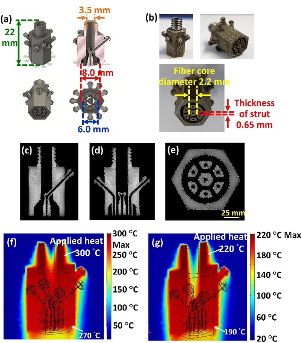
Figure 1.(a) Structured nozzle design including a 3D model, a cross section, and various views of the nozzle. (b) Side and bottom views of a metal 3D printed structured nozzle. Cross-section X-ray tomography images of the metal 3D printed nozzle in the (c)
3D printing has been adapted for operating with a range of metals, introducing the possibility of producing 3D-printed extrusion dies that can withstand extrusion forces and elevated temperatures. The geometrical freedom offered by 3D printing has been previously exploited for the fabrication of a metal extrusion die for the extrusion of optical fiber preforms from soft glasses [52]. Due to the small dimensions and complex internal structure of the structured nozzle, a metal 3D printer (ConceptLaser M2 metal printer) was selected to fabricate the nozzle. A thin layer of stainless-steel powder was spread over the build platform, and a high-power laser scanned the cross section of the designed nozzle to melt or fuse the metal particles together and create each layer. Layer after layer, the entire area of the model was scanned to produce the 3D solid shown in Fig. 1(b).
X-ray computed tomography was used to ensure that the narrow nozzle air-flow channels were fully formed throughout and that no residual unfused powder remained after the additive manufacturing process. A μCT machine (Nikon XT H 225) at the Centre for Precision Technologies, University of Huddersfield, was used to obtain 3D scans of internal features. The nozzle was mounted inside the μCT machine upon low density phenolic foam sponge, while 2D X-ray images were obtained from all sides of the part before reconstruction into a 3D density point cloud using CT Pro software. VG studio max was then used to separate the 3D printed material from low density air/foam based on grayscale density values using ISO50 automated surface determination to acquire an outline of the part. Lastly, a manual three-point planar registration tool was used to orient the scanned volume to the three planes of the CAD model so that slices through the , , and axes [Figs. 1(c), 1(d), and 1(e), respectively] can be created to verify all nozzle cooling channels are clear and features are fully formed throughout. This process proves that it is possible to design and metal 3D print the unique geometry of the structured nozzle for fabricating the microstructure optical fiber and that the models used for COMSOL heat transfer simulation are realistic.
The structured nozzle was fitted into the FDM 3D printer heater head. Heat from the heater cartridge (24 V, 35 W) was applied to the upper thread of the nozzle with a maximum temperature of . Heat transfer simulations of the structured nozzle were performed to optimize the length of the designed nozzle with various heater temperatures by using the COMSOL heat transfer module. The modeling results for the 22 mm long nozzle fabricated from stainless-steel CL20ES [Figs. 1(f) and 1(g)] indicated that the temperature at the nozzle tip is reduced from the applied to at the opposite extremity. When the heater is set to 220°C, the tip temperature decreased to 190°C. These temperatures are in the working range required for extruding the TOPAS (8007S-04) filament because the temperature at the tip of the nozzle is higher than its lowest melting temperature ().
4. EXPERIMENTAL SECTION
The HC-ARPF used in this experiment had an outer diameter of 8 mm and a 2.2 mm diameter hexagonal air core surrounded by a 0.65 mm thick layer [Fig. 2(a)]. The schematic of Fig. 2(b) shows a fiber cross section, where the gray shaded region is TOPAS, while the white region represents air. Waves propagating in the designed fiber are confined by the antiresonant effect: light is confined to the central air core, owing to the resonant reflection of the guided wave by the membrane interfaces surrounding the core, which behaves effectively as a Fabry–Perot cavity (the struts have a thickness of 0.65 mm in this fiber design).
![]()
Figure 2.(a) Bottom-view cross section of the nozzle. Yellow represents the area filled by the polymer. (b) Schematic of the cross section of the extruded TOPAS HC fiber.
To fabricate the HC-ARPF, the standard 3D printer nozzle was replaced by a metal 3D printed structured nozzle, which was connected to the heater block at the 3D printer head [Fig. 3(b)]. When the polymer is heated to a temperature higher than , the molecular chains experience a greater mobility, and the polymer macroscopic viscosity decreases significantly. Extrusion parameters have been investigated to optimize the feed rate and nozzle temperature, which have effect on the transparency and surface roughness of the extruded fiber and to find the fictive temperature for optimal fiber drawing. The optical quality of the extruded polymer was evaluated by extruding the filament through a nozzle as its temperature () was varied from 230°C to 290°C: at the polymer surface appeared smooth and shiny, with a significant reduction of bubble formation compared to other nozzle temperatures.
![]()
Figure 3.(a) Schematic of the experimental setup used to extrude the HC-ARPF from the 3D printer. (b) Photograph and (c) schematic of the HC-ARPF extruded from the heated structured nozzle.
The filament feed rate influences the effective temperature experienced by the polymer: slow feed rates result in high effective temperatures, and vice versa. A suitable combination of heater temperature and polymer feed rate was determined empirically from the fiber surface quality. The extrusion velocity was then varied, and an extruded fiber blank with a smooth surface was successfully achieved at and . The TOPAS HC-ARPF was fabricated by feeding the TOPAS filament using a built-in feeding motor operating at , corresponding to an extrusion speed of . Figure 3(a) shows the schematic of the microstuctured fiber drawing tower, which includes the FDM 3D printer head. The image and schematic of the extrusion of HC-ARPF from the structured nozzle are presented in Figs. 3(b) and 3(c).
To observe the cross section of the extruded HC-ARPF, the fiber was cleaved using an electric saw, and its surface was polished with sandpaper to reduce the surface roughness. The cross-section image of the extruded HC-ARPF showed that the microstructure inside fiber was maintained after the extrusion process [Figs. 4(a) and 4(b)].
![]()
Figure 4.(a) Cross-section and (b) photograph of the TOPAS hollow-core antiresonant THz fiber extruded from the metal 3D printed structured nozzle. (c) Schematic of the experimental setup used for characterization in the THz regime.
Optical properties of the solid-core microstructure polymer optical fiber (SC-MPOF) were characterized using THz time-domain spectroscopy (THz-TDS) [Fig. 4(c)]. To ensure a constant amount of light coupled into the fiber, the HC-ARPF was mounted in a custom-made holder, which included lenses to improve coupling, and clamps to fix the input end of the fiber at the lens focal point. A 2 mm diameter pinhole in the holder allowed us to launch the THz wave only into the fiber core. A second lens with a focal length of 50 mm was positioned at the other end of the holder for collimation. The THz source and detector used in this work are the same as reported in our previous THz setup for characterizing solid-core THz fiber [47]. The source and detector are active up to and , respectively, but the spectroscopic dynamic range is limited by ambient noise and component misalignment, which in particular limits the high end of the frequency range. The typical operation range of the spectrometer (achieved with the THz pulse in air) is .
5. RESULTS AND DISCUSSION
Mode coupling between core and cladding modes in HC-ARPFs occurs at resonant frequencies and results in high loss. The frequencies in the transmission window between resonant frequencies exhibit low loss, in which the modes are confined to the air core. The mode coupling occurs when the two modes are phase matched; therefore, the frequencies of these (high loss) resonances () can be calculated by the following formula [53]:
The confinement loss (CL) of the proposed THz fiber is given by the following formula [33]:
Loss in the HC-ARPFs is dominated by radiative mode leakage, since only a very small fraction of light, typically less than 0.1% at antiresonance, propagates in the solid material. As shown in Eq. (1) the optical properties of the HC-ARPFs, including resonant frequencies and transmission windows, can be controlled by varying the thickness of the strut surrounding the fiber core. The loss profile of the designed HC-ARPFs was calculated for different strut thicknesses of 0.55, 0.65, and 0.75 mm, while the core diameter was fixed at 2.5 mm. In order to evaluate the theoretical transmission characteristics of the HC-ARPF, finite element simulations (using the commercial FEM solver COMSOL Mode Solution) were performed by creating a model of the fiber cross-section structure with the same dimensions as the extruded fiber. The loss profiles in Fig. 5(a) indicate that the peak of the resonant frequencies shifts with the variation of strut thickness. For the HC-ARPFs, core diameter is one of the parameters that affect the fiber confinement loss: with the well-known HC fiber loss dependence [54], results in Fig. 5(b) show that the smaller core diameter results in higher confinement loss when the thickness of the strut is fixed at 0.65 mm. Therefore, to achieve low-loss guidance at the desired range of frequencies, both the thickness of struts and core diameter should be optimized. This can be simply achieved in the direct extrusion technique by applying pressure through the air holes and by controlling the nozzle temperature and material feeding speed.
![]()
Figure 5.(a) Simulation results (COMSOL) for the transmission loss of three HC-ARPFs with different strut thicknesses of 0.55, 0.65, and 0.75 mm. (b) Simulation results for transmission loss of three HC-ARPFs with different core diameters of 2.5, 3.0, and 3.5 mm when the thickness of strut is fixed at 0.65 mm.
By using (average refractive index in the range ), , and strut thickness t = 0.65 nm, the resonance frequencies in the range of interest (0.4–1.3 THz) at , 0.59, 0.74, 0.89, 1.04, and 1.19 THz can be calculated. The modal analysis of THz wave propagating through the HC-ARPF structure [Fig. 6(a)] shows that, at the resonant frequency (0.59 THz), the field of the THz wave is poorly confined in the central air core, and the mode in the fiber core is coupling with the surrounding material and leaks out to the cladding, resulting in high loss. Figure 6(b) shows that at the antiresonant frequency (0.7 THz) the field is confined in the central air core.
![]()
Figure 6.Simulated modal profiles in the fiber core at (a) resonant frequency (
The FEM loss spectra of this THz fiber calculated using COMSOL are shown in Fig. 6(c). Simulations indicate that the peaks of high loss are located at the resonant frequencies in the range , which coincide with the calculated values. As expected, field confinement becomes stronger as the frequency increases, as at lower frequencies the core size is small compared to the wavelength, pushing light into the surrounding material. This confirms that most of the power is confined within the central air core. To achieve low-loss guidance at specific frequencies, a different membrane thickness is needed. The loss at resonant frequencies can be significantly higher than the material loss, as the loss is dependent on the cladding geometry.
To confirm the THz guidance in the fabricated HC-ARPF, the fiber was characterized by THz time domain spectroscopy (TDS) [53]. Pulses from a femtosecond (fs) laser with the central wavelength at went through a beam splitter, and while one part of the fs-laser beam was directed through an optical delay line used to adjust the propagating time of the wave, the other irradiated the THz emitter, generating a THz beam. Figure 7(a) shows the time-domain spectrograms of the THz pulses passing through the air and after being collimated by a pair of polymethylpentene (TPX) lenses. The transmission level of the reference signal was performed by launching the THz wave through additional two TPX convex lenses to focus the THz beam, without any optical fiber. Then the optical fiber was characterized by launching the broadband THz wave into a 60 mm long section of the HC-ARPF using the THz focusing lens with focal length of 50 mm. At the focal point, the THz beam waist diameter was estimated to be at the frequency of 1 THz, comparable to the air-core diameter of the HC-ARPF. The train of fs-laser pulses from the time delay line and the transmitted THz wave from the fiber were simultaneously shone onto the THz detector to detect the signal using the THz-TDS detector. The wave transmitted by the fiber was recorded in the time domain, and a subsequent Fourier transform allowed generation of a transmission spectrum in the frequency domain. The Fourier transform spectra of the THz wave from the THz emitter (black line) and when it was launched through the lens (red line) are presented in Fig. 7(b). When the THz wave was launched through the lens, the amplitude of the transmission spectrum was dramatically decreased in comparison with the spectrum from the THz emitter, due to the material absorption of the lens and its related coupling efficiency. The transmission spectrum of the THz wave guided in the 60 mm long HC-ARPF is reported in Fig. 7(b) (blue line). When compared with the spectrum from the THz emitter, troughs of high loss at the resonant frequencies can be clearly observed. The peaks of low loss (antiresonant frequencies) are also visible as indicated in Fig. 7(b). These windows are the antiresonant frequencies window between two consecutive resonances windows with high loss.
![]()
Figure 7.(a) Time-domain measurement of the THz wave from THz emitter (collimated beam). (b) Spectral profile of the THz wave from the emitter (black line), when it passes through two THz convex lenses (red line) and when it is transmitted through the HC-ARPF (blue line). (c)–(e) Spectrograms of the THz wave (c) from the THz emitter, (d) after propagating through two THz convex lenses, and (e) through the two convex lenses and a 60 mm long HC-ARPF.
The spectrogram (time-frequency plot) was analyzed from the time domain of the THz output signal by using a sliding Gaussian-shaped sample window of 128 samples. To achieve the spectrogram, the windowed time-domain signals were then Fourier transformed into the frequency domain, and then spectral components will be plotted against the signal time delay. The spectrogram from the THz emitter indicates that the pulse of THz wave aggregates at around the arrival time . The spectrogram shows that this THz emitter has an effective bandwidth over which useful spectroscopic data can be obtained, ranging in the frequency range [Fig. 7(c)]. As presented in Fig. 7(d), the THz wave propagated through two convex lenses and arrived at the detector at . The slowdown in the pulse velocity is due to the higher refractive index of the lens. The temporal components that propagated through the 60 mm long HC-ARPF arrived at [Fig. 7(e)]. The time arrival of the THz wave from the fiber is 2 ps slower than that of the reference signal, which confirms the guiding of the THz wave in the air core of the fiber. The increase in time delay when the THz wave propagated through the fiber is due to the overlap of the guided mode with the high index material surrounding the core.
Fiber propagation losses were measured using the cut-back method. Three HC-ARPF sections were fabricated with different lengths of 40, 60, and 80 mm. The transmission of the THz wave through the fiber of different lengths was measured using a MenloSystems TERA8-1 photoconductive antenna. To maintain consistency during these measurements, all three optical fibers were aligned using the modified cylindrical fiber holder. The transmission through each length of fiber was measured 3 times and averaged to reduce the effect of the difference in coupling for each attempt. The results show that the transmission at the frequencies within the guiding window [green highlight in Fig. 8(a)] decreases significantly for increasing fiber lengths. The resulting data was also analyzed using a spectrogram, which provides a clear view of the decreasing signal amplitude from the fiber output occurring due to different fiber lengths [Figs. 8(b)–8(d)]. To study the performance of the waveguide further, confinement loss of the extruded HC-ARPF was experimentally analyzed. The comparison between the simulated (red line) and measured (black line) loss can be seen in Fig. 8(e): two antiresonant windows can be clearly seen at the expected spectral regions around and 0.7 THz, while simulations of confinement loss revealed four antiresonant windows. This discrepancy can be explained by the characteristics of the THz source that has low intensity at . Although only two antiresonant windows can be experimentally observed, their location is in good agreement with the simulations. Confinement loss at the antiresonant frequencies from experiments is also close to the simulated value of at .
![]()
Figure 8.(a) Spectral profile of the THz waves from the HC-ARPF with the lengths of 40, 60, and 80 mm. Spectrograms of the THz wave from THz HC-ARPF with lengths of (b) 40 mm, (c) 60 mm, and (d) 80 mm. (e) Experimental result and numerical simulation of the loss for the TOPAS HC-ARPF.
6. CONCLUSIONS
In conclusion, a TOPAS hollow-core antiresonant fiber fabricated by a direct extrusion technique using a 3D printer has been demonstrated. By using this technique, 1 m of fiber was fabricated within 30 min. Given the relatively low cost and ease of operation, compared to a conventional drawing tower, desktop 3D printers may become an invaluable tool for the production of microstructured optical fibers. The microstructured extrusion die can be fabricated by using a metal 3D printer. The metal 3D printed nozzle withstood the temperature of 300°C and high force, demonstrating that 3D printed structured nozzles have sufficient mechanical strength to enable extrusion of optical fibers. Compare with our previous work in which the structured nozzle was fabricated using the micromachining technique, the metal 3D printed nozzle allows us to fabricate any complex structure of optical fiber. Analysis of the fiber produced in this work proved the ability to maintain the fiber geometry after extrusion from a customized 3D printer head. The modal profile simulations showed the ability of the fiber to confine THz waves at the antiresonant frequencies in the air core. Time and frequency domain spectrograms also confirmed air-core guidance of the proposed HC fiber. By fabricating the THz HC-ARPF from TOPAS polymer, the confinement loss of the extruded HC-ARPF was measured to be 0.12 dB/cm at 0.7 THz. Both simulations and experimental loss profile revealed a potential to use the extruded fiber as THz waveguide in the spectral range 0.4–1.0 THz.
Acknowledgment
Acknowledgment. W. Talataisong received her student scholarship by the Development and Promotion of Science and Technology Talents Project (Royal Thai Government scholarship). W. Talataisong thanks Mr. Richard Dooler, an engineer in the mechanical workshop, at the University of Southampton, for his effort in fabricating the metal 3D printed nozzle. This work is also supported by Suranaree University of Technology and Thailand Science Research and Innovation (TSRI). The authors gratefully acknowledge TOPAS Advanced Polymers GmbH in Germany for providing us with the first TOPAS polymer for this research project.
References
[1] J. F. Federici, B. Schulkin, F. Huang, D. Gary, R. Barat, F. Oliveira, D. Zimdars. THz imaging and sensing for security applications—explosives, weapons and drugs. Semicond. Sci. Technol., 20, S266-S280(2005).
[2] G. C. Trichopoulos, H. L. Mosbacker, D. Burdette, K. Sertel. A broadband focal plane array camera for real-time THz imaging applications. IEEE Trans. Antennas Propag., 61, 1733-1740(2013).
[3] U. R. Pfeiffer, Y. Zhao, J. Grzyb, R. A. Hadi, N. Sarmah, W. Förster, H. Rücker, B. Heinemann. 14.5 A 0.53 THz reconfigurable source array with up to 1 mW radiated power for terahertz imaging applications in 0.13 μm SiGe BiCMOS. IEEE International Solid-State Circuits Conference (ISSCC), 256-257(2014).
[4] E. V. Yakovlev, K. I. Zaytsev, I. N. Dolganova, S. O. Yurchenko. Non-destructive evaluation of polymer composite materials at the manufacturing stage using terahertz pulsed spectroscopy. IEEE Trans. Terahertz Sci. Technol., 5, 810-816(2015).
[5] D. M. Mittleman. Twenty years of terahertz imaging [Invited]. Opt. Express, 26, 9417-9431(2018).
[6] M. Zhang, J. T. W. Yeow. Nanotechnology-based terahertz biological sensing: a review of its current state and things to come. IEEE Nanatechnol. Mag., 10, 30-38(2016).
[7] M. Borovkova, M. Khodzitsky, P. Demchenko, O. Cherkasova, A. Popov, I. Meglinski. Terahertz time-domain spectroscopy for non-invasive assessment of water content in biological samples. Biomed. Opt. Express, 9, 2266-2276(2018).
[8] K. Wang, D. M. Mittleman. Metal wires for terahertz wave guiding. Nature, 432, 376-379(2004).
[9] M. S. Islam, J. Sultana, K. Ahmed, M. R. Islam, A. Dinovitser, B. W. Ng, D. Abbott. A novel approach for spectroscopic chemical identification using photonic crystal fiber in the terahertz regime. IEEE Sens. J., 18, 575-582(2018).
[10] D. F. Swearer, S. Gottheim, J. G. Simmons, D. J. Phillips, M. J. Kale, M. J. McClain, P. Christopher, N. J. Halas, H. O. Everitt. Monitoring chemical reactions with terahertz rotational spectroscopy. ACS Photon., 5, 3097-3106(2018).
[11] P. Doradla, C. Joseph, R. H. Giles. Terahertz endoscopic imaging for colorectal cancer detection: current status and future perspectives. World J. Gastrointest. Endosc., 9, 346-358(2017).
[12] I. F. Akyildiz, J. M. Jornet, C. Han. Terahertz band: next frontier for wireless communications. Phys. Commun., 12, 16-32(2014).
[13] B. Moyna. Terahertz and millimetre-wave receivers and radiometers.
[14] S. U. Hwu, K. B. deSilva, C. T. Jih. Terahertz (THz) wireless systems for space applications. IEEE Sensors Applications Symposium Proceedings, 171-175(2013).
[15] S. S. Dhillon, M. S. Vitiello, E. H. Linfield, A. G. Davies, M. C. Hoffmann, J. Booske, C. Paoloni, M. Gensch, P. Weightman, G. P. Williams, E. Castro-Camus, D. R. S. Cumming, F. Simoens, I. Escorcia-Carranza, J. Grant, S. Lucyszyn, M. Kuwata-Gonokami, K. Konishi, M. Koch, C. A. Schmuttenmaer, T. L. Cocker, R. Huber, A. G. Markelz, Z. D. Taylor, V. P. Wallace, J. A. Zeitler, J. Sibik, T. M. Korter, B. Ellison, S. Rea, P. Goldsmith, K. B. Cooper, R. Appleby, D. Pardo, P. G. Huggard, V. Krozer, H. Shams, M. Fice, C. Renaud, A. Seeds, A. Stöhr, M. Naftaly, N. Ridler, R. Clarke, J. E. Cunningham, M. B. Johnston. The 2017 terahertz science and technology roadmap. J. Phys. D, 50, 043001(2017).
[16] D. W. Vogt, R. Leonhardt. 3D-printed broadband dielectric tube terahertz waveguide with anti-reflection structure. J. Infrared Millim. Terahertz Waves, 37, 1086-1095(2016).
[17] S. R. Andrews. Microstructured terahertz waveguides. J. Phys. D, 47, 374004(2014).
[18] R. Khabibullin, D. Ushakov, A. Afonenko, N. Shchavruk, D. Ponomarev, O. Volkov, V. Pavlovskiy, I. Vasil’evskii, D. Safonov, A. Dubinov. Silver-based double metal waveguide for terahertz quantum cascade laser. Proc. SPIE, 11022, 1102204(2019).
[19] B. You, J.-Y. Lu. Remote and in situ sensing products in chemical reaction using a flexible terahertz pipe waveguide. Opt. Express, 24, 18013-18023(2016).
[20] G. C. Trichopoulos, K. Sertel. Polarimetric terahertz probe for endoscopic assessment of malignancies. IEEE International Symposium on Antennas and Propagation & USNC/URSI National Radio Science Meeting, 730-731(2015).
[21] B. Ung, A. Mazhorova, A. Dupuis, M. Rozé, M. Skorobogatiy. Polymer microstructured optical fibers for terahertz wave guiding. Opt. Express, 19, B848-B861(2011).
[22] A. Argyros. Microstructures in polymer fibres for optical fibres, THz waveguides, and fibre-based metamaterials. ISRN Opt., 2013, 785162(2013).
[23] R. Mendis, D. Grischkowsky. Plastic ribbon THz waveguides. J. Appl. Phys., 88, 4449-4451(2000).
[24] H. Han, H. Park, M. Cho, J. Kim. Terahertz pulse propagation in a plastic photonic crystal fiber. Appl. Phys. Lett., 80, 2634-2636(2002).
[25] M. Goto, A. Quema, H. Takahashi, S. Ono, N. Sarukura. Teflon photonic crystal fiber as terahertz waveguide. Jpn. J. Appl. Phys., 43, L317-L319(2004).
[26] K. Nielsen, H. K. Rasmussen, A. J. L. Adam, P. C. M. Planken, O. Bang, P. U. Jepsen. Bendable, low-loss Topas fibers for the terahertz frequency range. Opt. Express, 17, 8592-8601(2009).
[27] Q. Chen, Y. Zhang, X. He, D. Kong, J. Zhang. Design and fabrication of cyclic-olefin copolymer based terahertz hollow-core photonic crystal fiber. 38th International Conference on Infrared, Millimeter, and Terahertz Waves (IRMMW-THz), 1-2(2013).
[28] Q. Chen, W. Zhu, D. Kong, X. He, B. Li, J. Miao, Z. Luo, X. Zhou, C. Yang, J. Zhang. Development of 2.5 THz suspended porous microstructured fiber based on cyclic-olefin copolymer. Optik, 145, 56-60(2017).
[29] M. S. Islam, J. Sultana, J. Atai, D. Abbott, S. Rana, M. R. Islam. Ultra low-loss hybrid core porous fiber for broadband applications. Appl. Opt., 56, 1232-1237(2017).
[30] C. M. Smith, N. Venkataraman, M. T. Gallagher, D. Müller, J. A. West, N. F. Borrelli, D. C. Allan, K. W. Koch. Low-loss hollow-core silica/air photonic bandgap fibre. Nature, 424, 657-659(2003).
[31] M. Navarro-Cía, M. S. Vitiello, C. M. Bledt, J. E. Melzer, J. A. Harrington, O. Mitrofanov. Terahertz wave transmission in flexible polystyrene-lined hollow metallic waveguides for the 2.5-5 THz band. Opt. Express, 21, 23748-23755(2013).
[32] L. D. van Putten, J. Gorecki, E. N. Fokoua, V. Apostolopoulos, F. Poletti. 3D-printed polymer antiresonant waveguides for short-reach terahertz applications. Appl. Opt., 57, 3953-3958(2018).
[33] S. Yan, S. Lou, X. Wang, T. Zhao, W. Zhang. High-birefringence hollow-core anti-resonant THz fiber. Opt. Quantum Electron., 50, 162(2018).
[34] S. Atakaramians, S. A. Vahid, T. M. Monro, D. Abbott. Terahertz dielectric waveguides. Adv. Opt. Photon., 5, 169-215(2013).
[35] A. Stefani, S. C. Fleming, B. T. Kuhlmey. Terahertz orbital angular momentum modes with flexible twisted hollow core antiresonant fiber. APL Photon., 3, 051708(2018).
[36] A. L. S. Cruz, C. M. B. Cordeiro, M. A. R. Franco. 3D printed hollow-core terahertz fibers. Fibers, 6, 43(2018).
[37] S. Atakaramians, S. A. Vahid, H. Ebendorff-Heidepriem, M. Nagel, B. M. Fischer, D. Abbott, T. M. Monro. THz porous fibers: design, fabrication and experimental characterization. Opt. Express, 17, 14053-14062(2009).
[38] X. Feng, T. M. Monro, V. Finazzi, R. C. Moore, K. Frampton, P. Petropoulos, D. J. Richardson. Extruded singlemode, high-nonlinearity, tellurite glass holey fibre. Electron. Lett., 41, 835-837(2005).
[39] H. Ebendorff-Heidepriem, T. M. Monro, M. A. van Eijkelenborg, M. C. J. Large. Extruded high-NA microstructured polymer optical fibre. Opt. Commun., 273, 133-137(2007).
[40] H. Ebendorff-Heidepriem, T. M. Monro. Extrusion of complex preforms for microstructured optical fibers. Opt. Express, 15, 15086-15092(2007).
[41] S. Atakaramians, K. Cook, H. Ebendorff-Heidepriem, S. A. Vahid, J. Canning, D. Abbott, T. M. Monro. Cleaving of extremely porous polymer fibers. IEEE Photon. J., 1, 286-292(2009).
[42] S. J. Young, P. J. Yong, L. Chenyang, H. Jiasong, K. S. Chul. Chemical structure and physical properties of cyclic olefin copolymers (IUPAC Technical Report). Pure Appl. Chem., 77, 801-814(2005).
[43] G. Khanarian. Optical properties of cyclic olefin copolymers. Opt. Eng., 40, 1024-1029(2001).
[44] Engineering ToolBox. Young’s modulus–tensile and yield strength for common materials(2003).
[45] S. F. Busch, M. Weidenbach, J. C. Balzer, M. Koch. THz optics 3D printed with TOPAS. J. Infrared Millim. Terahertz Waves, 37, 303-307(2016).
[46] J. C. S. Ponseca, R. Pobre, E. Estacio, N. Sarukura, A. Argyros, M. C. Large, M. A. van Eijkelenborg. Transmission of terahertz radiation using a microstructured polymer optical fiber. Opt. Lett., 33, 902-904(2008).
[47] W. Talataisong, J. Gorecki, R. Ismaeel, M. Beresna, D. Schwendemann, V. Apostolopoulos, G. Brambilla. Singlemoded THz guidance in bendable TOPAS suspended-core fiber directly drawn from a 3D printer. Sci. Rep., 10, 11045(2020).
[48] W. Talataisong, R. Ismaeel, S. R. Sandoghchi, T. Rutirawut, G. Topley, M. Beresna, G. Brambilla. Novel method for manufacturing optical fiber: extrusion and drawing of microstructured polymer optical fibers from a 3D printer. Opt. Express, 26, 32007-32013(2018).
[49] P. Petropoulos, H. Ebendorff-Heidepriem, V. Finazzi, R. C. Moore, K. Frampton, D. J. Richardson, T. M. Monro. Highly nonlinear and anomalously dispersive lead silicate glass holey fibers. Opt. Express, 11, 3568-3573(2003).
[50] H. Ebendorff-Heidepriem, P. Petropoulos, S. Asimakis, V. Finazzi, R. C. Moore, K. Frampton, F. Koizumi, D. J. Richardson, T. M. Monro. Bismuth glass holey fibers with high nonlinearity. Opt. Express, 12, 5082-5087(2004).
[51] J. Y. Y. Leong, P. Petropoulos, J. H. V. Price, H. Ebendorff-Heidepriem, S. Asimakis, R. C. Moore, K. E. Frampton, V. Finazzi, X. Feng, T. M. Monro, D. J. Richardson. High-nonlinearity dispersion-shifted lead-silicate holey fibers for efficient 1-μm pumped supercontinuum generation. J. Lightwave Technol., 24, 183-190(2006).
[52] H. Ebendorff-Heidepriem, J. Schuppich, A. Dowler, L. Lima-Marques, T. M. Monro. 3D-printed extrusion dies: a versatile approach to optical material processing. Opt. Mater. Express, 4, 1494-1504(2014).
[53] W. Lu, A. Argyros. Terahertz spectroscopy and imaging with flexible tube-lattice fiber probe. J. Lightwave Technol., 32, 4621-4627(2014).
[54] J. R. Hayes, F. Poletti, D. J. Richardson. Optimising the performances of hollow antiresonant fibres. 37th European Conference and Exposition on Optical Communications, Mo.2.LeCervin.2(2011).

Set citation alerts for the article
Please enter your email address
© Copyright 2018-2021 | Chinese Laser Press. All Rights Reserved 沪ICP备15018463号-20