
Wanvisa Talataisong, Jon Gorecki, Lieke D. van Putten, Rand Ismaeel, James Williamson, Katie Addinall, Daniel Schwendemann, Martynas Beresna, Vasilis Apostolopoulos, Gilberto Brambilla. Hollow-core antiresonant terahertz fiber-based TOPAS extruded from a 3D printer using a metal 3D printed nozzle[J]. Photonics Research, 2021, 9(8): 1513
- Photonics Research
- Vol. 9, Issue 8, 1513 (2021)
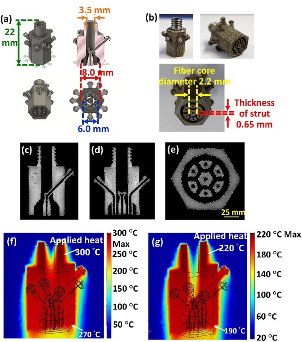
Fig. 1. (a) Structured nozzle design including a 3D model, a cross section, and various views of the nozzle. (b) Side and bottom views of a metal 3D printed structured nozzle. Cross-section X-ray tomography images of the metal 3D printed nozzle in the (c) x y z T = 300 ° C T = 220 ° C
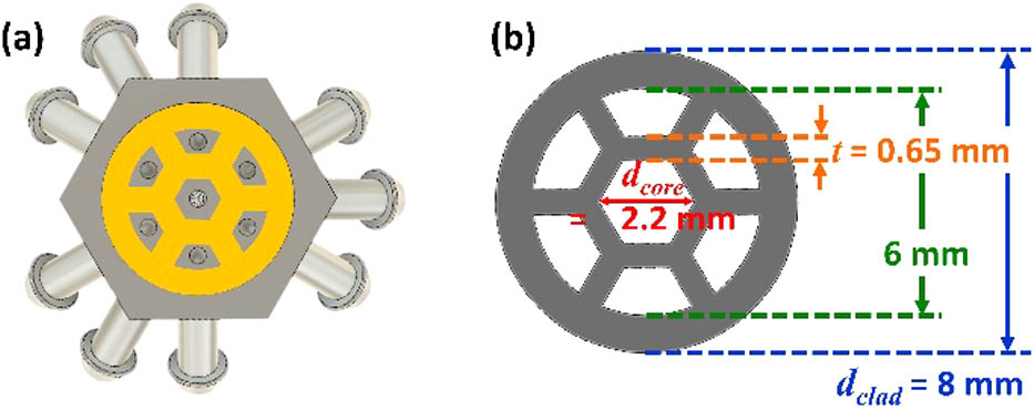
Fig. 2. (a) Bottom-view cross section of the nozzle. Yellow represents the area filled by the polymer. (b) Schematic of the cross section of the extruded TOPAS HC fiber.
Fig. 3. (a) Schematic of the experimental setup used to extrude the HC-ARPF from the 3D printer. (b) Photograph and (c) schematic of the HC-ARPF extruded from the heated structured nozzle.
Fig. 4. (a) Cross-section and (b) photograph of the TOPAS hollow-core antiresonant THz fiber extruded from the metal 3D printed structured nozzle. (c) Schematic of the experimental setup used for characterization in the THz regime.
Fig. 5. (a) Simulation results (COMSOL) for the transmission loss of three HC-ARPFs with different strut thicknesses of 0.55, 0.65, and 0.75 mm. (b) Simulation results for transmission loss of three HC-ARPFs with different core diameters of 2.5, 3.0, and 3.5 mm when the thickness of strut is fixed at 0.65 mm.
Fig. 6. Simulated modal profiles in the fiber core at (a) resonant frequency (ν = 0.59 THz ν = 0.70 THz d = 2.2 mm t = 0.65 mm
Fig. 7. (a) Time-domain measurement of the THz wave from THz emitter (collimated beam). (b) Spectral profile of the THz wave from the emitter (black line), when it passes through two THz convex lenses (red line) and when it is transmitted through the HC-ARPF (blue line). (c)–(e) Spectrograms of the THz wave (c) from the THz emitter, (d) after propagating through two THz convex lenses, and (e) through the two convex lenses and a 60 mm long HC-ARPF.
Fig. 8. (a) Spectral profile of the THz waves from the HC-ARPF with the lengths of 40, 60, and 80 mm. Spectrograms of the THz wave from THz HC-ARPF with lengths of (b) 40 mm, (c) 60 mm, and (d) 80 mm. (e) Experimental result and numerical simulation of the loss for the TOPAS HC-ARPF.

Set citation alerts for the article
Please enter your email address
© Copyright 2018-2021 | Chinese Laser Press. All Rights Reserved 沪ICP备15018463号-20