
Taifei Zhao, Dandan Cao, Qianwen Ma. Optimally Rigid Formation Generation Algorithm Based on Ultraviolet Optical Communication for UAVs[J]. Laser & Optoelectronics Progress, 2021, 58(5): 0506001
- Laser & Optoelectronics Progress
- Vol. 58, Issue 5, 0506001 (2021)

Fig. 1. Formation network model of UAV
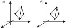
Fig. 2. Flexible and rigid frameworks. (a) Flexible graph; (b) rigid graph
Fig. 3. UV ALOS communication link model
Fig. 4. Flowchart of UVORF algorithm
Fig. 5. Hemispherical communication node structure
Fig. 6. Local topology composed of node A and its neighbors. (a) Initial topology; (b) optimal rigid topology
Fig. 7. Curves of neighbor discovery success probability.
Fig. 8. Formation topologies derived by different algorithms. (a) Maximum power topology; (b) UVORF; (c) GG3D; (d) RNG3D
Fig. 9. Comparison of average node degree
Fig. 10. Comparison of node degree. (a) Maximum node degree; (b) minimum node degree
Fig. 11. Comparison of average communication radius
|
Table 1. Neighbor information of node
|
Table 2. Pseudo-code of topology construction
|
Table 3. Weights of links after ascending sequence
|
Table 4. Part simulation parameters

Set citation alerts for the article
Please enter your email address
© Copyright 2018-2021 | Chinese Laser Press. All Rights Reserved 沪ICP备15018463号-20