Leonid L. Doskolovich1,2,*, Evgeni A. Bezus1,2, and Dmitry A. Bykov1,2
Abstract
We propose a simple integrated narrowband filter consisting of two grooves on the surface of a slab waveguide. Spectral filtering is performed in transmission at oblique incidence due to excitation of an eigenmode of the structure localized at a ridge cavity between the grooves. For the considered parameters, zero reflectance and unity transmittance are achieved at resonant conditions. The width and location of the transmittance peak can be controlled by changing the widths of the grooves and of the ridge, respectively. The proposed filter may find application in waveguide-integrated spectrometers.1. INTRODUCTION
Spectral and spatial filters that selectively transmit or reflect input light are indispensable in various optical devices including spectrum analyzers, image sensors, wavelength demultiplexers, LCDs, and remote sensing systems. In a wide class of planar (integrated) optoelectronic systems, spectral or spatial filtering is performed in a slab waveguide [1–7]. Such geometry corresponds to the “insulator-on-insulator” platform and is suitable for the creation of fully integrated optical devices. In Refs. [1,8–12], planar Bragg gratings (BGs) and phase-shifted Bragg gratings (PSBGs) were proposed for spectral filtering of optical radiation propagating along the waveguide. A planar BG corresponds to a single-mode slab waveguide with an appropriate periodically corrugated surface and acts as a reflection filter centered at the Bragg wavelength. A change in the waveguide thickness leads to a change in the effective refractive index of the guided mode and makes it possible to encode the required refractive index distribution analogous to a free-space BG. A planar PSBG consists of two or more symmetric BGs separated by defects (phase-shift regions) and makes it possible to obtain a narrow transmission peak at the center of the stop band [1,11,12].
Recently, novel structures that can be applied in integrated spectrometers, the so-called digital planar holograms (DPHs), were proposed [3–6]. DPHs correspond to a sophisticated superposition of narrowband curvilinear BG-based reflectors fabricated on the surface of the waveguide layer. The curvilinear (e.g., elliptic) shape of the reflectors makes it possible to perform spatially resolved spectral filtering; radiation with different wavelengths is focused at different points. It is important to note that the methods for designing DPHs are a know-how of the authors and are not described in detail in the published works.
In this work, we propose a planar spectral filter consisting of two grooves on the surface of a slab waveguide and operating in transmission. In contrast to the PSBG-based filters, our filter has a much simpler geometry and is substantially more compact.
Sign up for Photonics Research TOC. Get the latest issue of Photonics Research delivered right to you!Sign up now
2. GEOMETRY OF THE STRUCTURE
The proposed filter is a planar version of a dielectric three-layer resonant structure [Fig. 1(a)], which was studied in Ref. [13] for achieving large optical field enhancement over a large volume. A similar dielectric–metal–dielectric structure has been shown to tunnel light through metal layers [14]. The structure in Fig. 1(a) consists of a central layer (refractive index , thickness ) and two identical cladding layers (refractive index , thickness ).
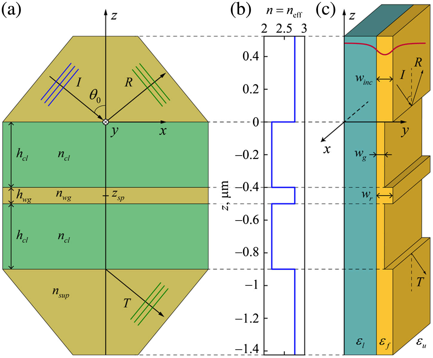
Figure 1.Geometry of (a) a conventional three-layer resonant structure and (c) the proposed two-groove planar filter, and (b) the refractive (effective refractive) index profile of the structure. The values in (b) and dimensions in (c) correspond to one of the examples described in the text. I, R, and T denote incident, reflected, and transmitted waves, respectively.
If the refractive index of the surrounding medium satisfies the condition , at a certain angle of incidence the structure may exhibit unity resonant transmission due to coupling of the incident light to a waveguide mode localized at the central layer, which in this case acts as a resonant cavity [13]. Let us note that the unity resonant transmission condition can be strictly satisfied only if the resonant structure has a horizontal symmetry plane [Fig. 1(a)] [15,16]. In this case, the structure corresponds to a so-called W-type waveguide [17]. At a significantly large cladding thickness , the leaky mode of the W-type structure can be approximately described by the dispersion relation of the modes of a slab waveguide, which becomes exact at infinite . In this case, the excitation of the mode of the structure in Fig. 1(a) will occur in the vicinity of the frequency and the tangential component of the wave vector, which satisfy the dispersion relation of a slab waveguide [18]. Therefore, at resonant conditions the reflection coefficient will vanish at certain and values close to and , respectively. It is worth noting that the quality factor of the resonance (the width of the resonant transmission peak) is determined by the thickness of the cladding layer [13].
The analysis presented indicates that the structure presented in Fig. 1(a) may be used as a spectral or spatial (angular) narrowband transmission filter. However, despite the simple geometry of the structure, it has several disadvantages concerning its practical use. In particular, due to the condition , such a filter requires the use of two high-index prisms for incoupling and outcoupling of the incident optical beam, and thus cannot be highly integrated.
At the same time, this structure can serve as a prototype for designing a simple planar filter integrated into a slab waveguide. The waveguide considered has the following parameters: a dielectric permittivity and thickness of the core layer of and , respectively, and dielectric permittivities of the claddings of and . As a planar analogue of the three-layer structure of Fig. 1(a), we propose to use the structure consisting of two grooves on a waveguide surface shown in Fig. 1(c). The length of the grooves and of the ridge between them is equal to the thickness of a layer of the conventional structure for free-space radiation.
Let us denote by and the thicknesses of the waveguide in the groove and ridge regions, respectively (). At a fixed frequency , the effective refractive index of the guided mode is a function of the core layer thickness . Thus, the proposed planar structure can be considered as a direct analogue of a conventional structure with the refractive indices , , [Fig. 1(b)]. In all the examples considered, , so . Since the function is monotonically increasing [18], .
3. RESULTS AND DISCUSSION
Let us numerically study the performance of the proposed two-groove planar filter (TGPF). In all the simulations, the following parameters were used: free-space wavelength , , (fused silica), , . At these parameters, the slab waveguide is single-mode. The TGPF consists of two grooves with a depth of (so that ) and a ridge between them. In the case of TE polarization, the effective refractive index of the incident guided mode and the mode in the ridge region is , while the effective refractive index in the groove region is .
The resonances occurring in the proposed TGPF are associated with the excitation of a leaky eigenmode localized at the cavity corresponding to the central ridge and propagating along the axis. In this case, this mode is close to the mode of a photonic wire waveguide. The quality factor of the resonance (the width of the resonant peak) is determined by the width of the grooves . To illustrate this, we calculated the angular and wavelength transmission spectra of the investigated structure at two groove widths, and (Fig. 2). As shown below, at these groove widths the angular and spectral widths of the resonant peaks differ by approximately a factor of 10. The width of the ridge is fixed and equals . The spectra were calculated using an in-house implementation of the aperiodic rigorous coupled-wave analysis (aRCWA) technique [19]. RCWA, also called the Fourier modal method, is an established numerical technique for solving Maxwell’s equations. The angular spectra in Fig. 2(a) were calculated at a fixed wavelength . The transmittance reaches unity at the angles of incidence (at ) and (at ). The full widths at half maximum (FWHMs) of the resonant transmittance peaks amount to and at and , respectively. The dependence of the FWHM of the resonant peak on the width is shown in the inset. Let us note that the angles of incidence depend on the thickness of the waveguide in the groove regions . With a decrease in [decrease in ], the angles also decrease, and at [ in the groove regions], they approach 33°.

Figure 2.(a) Angular and (b) wavelength TGPF transmission spectra at (dashed blue curves) and (solid red curves). The insets show the FWHM of the resonant peaks versus .
It is worth noting that in the case of incidence of a TE-polarized mode at angles of incidence greater than , there is no out-of-plane scattering and polarization conversion in the structure. Indeed, one can show that at the slab waveguide does not support any propagating TM-polarized modes with the propagation constants , where and is the tangential component of the wave vector of the incident TE-polarized mode. Moreover, the plane waves under and over the structure (in the regions with dielectric permittivities and ) with the wave vector component are evanescent. Thus, the energy of the incident TE-polarized mode will be divided only between two modes (reflected and transmitted) having the same polarization. Due to this, zero reflectance and unity transmittance are achieved in the structure at resonant conditions [15].
The wavelength spectra in Fig. 2(b) were calculated at the angles of incidence and , taking into account the dielectric permittivity dispersion of the core layer. FWHM values of the resonant peaks are (at ) and (at ). Similar to Fig. 2(a), the inset in Fig. 2(b) shows the FWHM of the peak versus the width .
To further investigate the resonances associated with the transmittance peaks in Fig. 2, we calculated complex-wavelength eigenmodes of the TGPF corresponding to the poles of the transmission coefficient using the method presented in Ref. [20]. The obtained values at and at are in the vicinity of the wavelength . Since the spectra in Fig. 2(b) have a Lorentzian line shape, the values and can be used to estimate the widths of the resonant peaks at half maximum. These values are in good agreement with the and values given above. Figure 3 shows the distributions of the component of the electromagnetic field at in the case of diffraction of the TE-polarized mode on the TGPF at three wavelengths: 600 nm (away from the resonance), 620 nm (closer to the resonance), and 630 nm (at the resonance). The angle of incidence is fixed at . The distributions are normalized by the maximum intensity of the component of the incident guided mode. At the wavelengths 600 and 620 nm, the incident mode is almost completely reflected; the interference of the incident and reflected modes is clearly visible in Figs. 3(a) and 3(b). At 630 nm, a leaky eigenmode is excited at the ridge cavity between the grooves [Fig. 3(c)], and resonant unity transmittance is achieved. The incident and transmitted waves are not visible in Fig. 3(c) due to the field enhancement at the cavity. It is worth noting that the field distribution in Fig. 3(c) is visually identical to the field distribution of the leaky eigenmode of the structure.
Figure 3.Distributions of the component of the electromagnetic field in the TGPF normalized by the maximum value of the incident guided mode at and for the free-space wavelengths (a) 600, (b) 620, and (c) 630 nm.
In the design of micro-spectrometers and hyperspectral sensors, so-called linear variable filters (LVFs) are widely used. An LVF is a bandpass filter that is intentionally wedged in one direction, providing a position-dependent dispersive optical element. Typically, the LVF corresponds to a Fabry–Perot etalon with varying thickness between two Bragg reflectors [21–24]. On the basis of the proposed TGPF, a waveguide-integrated LVF can be created, in which the spectral shift of the transmittance peak can be achieved by changing one of the parameters of the structure, e.g., the ridge width . Figure 4 shows the ability to control the location of the peak by changing the value. In the example, the peak is shifted by approximately 7 nm if the value is changed by 2.5 nm.
Figure 4.Calculated transmittance spectra at varying ridge widths ranging from 87.5 nm (leftmost peak) to 112.5 nm (rightmost peak) in steps of 2.5 nm. Colors of the curves correspond to the resonant wavelengths at each ridge width value.
The examples given demonstrate that the proposed TGPF enables us to obtain a narrow transmission peak with a subnanometer spectral width and Lorentzian line shape. In practical applications, achieving a nearly rectangular transmittance peak with a flat transmission band and steep slopes is highly desirable [11]. In PSBG-based filters, this problem is solved by introducing several properly chosen phase-shift regions. A similar approach can be applied for the considered TGPF.
As a simple example, let us consider a filter composed of two concatenated TGPFs with and separated by an additional phase-shift ridge with a width of 198 nm (inset in Fig. 5). Following the approach used in Ref. [25] for the analysis of reflectance spectra of stacked PSBGs, the width of the phase-shift ridge was chosen so that the reflectance spectrum of the structure possesses a so-called second-order zero. In terms of the transmittance spectrum, this leads to a shape of the resonant peak that is significantly closer to a rectangle (Fig. 5).
Figure 5.Transmittance spectra of the TGPF with , (dashed blue curve), and of the planar structure consisting of two TGPFs separated by an additional groove with a width of 198 nm (shown in the inset) (solid red curve).
The calculations [20] show that the concatenated structure supports two closely located modes with the complex wavelengths (even mode) and (odd mode). The even and odd modes of the concatenated structure correspond to the in-phase and out-of-phase excitation, respectively, of the individual TGPFs’ modes. Note that the complex wavelengths satisfy the condition , which provides the so-called flat-top resonance line shape [26]. The quality factors of the modes of the concatenated structure are twice the quality factor of the mode of the initial structure (). As the result, the FWHM value for the concatenated structure decreases, and in our example amounts to 0.22 nm instead of 0.3 nm for the initial structure. A further improvement in the peak shape can be achieved by increasing the number of concatenated TGPFs, similar to the approach used for PSBG-based filters [11].
4. CONCLUSION
In summary, in the present work we proposed a simple narrowband transmission filter consisting of two grooves on the surface of a slab waveguide and intended for spectral filtering of optical radiation propagating in the waveguide. The spectral filtering is performed due to the resonant excitation of an eigenmode of the structure localized at the cavity corresponding to the ridge between the grooves. On the basis of rigorous numerical simulations, the ability to control the spectral width and location of the transmittance peak by changing the widths of the grooves and the ridge between them was demonstrated. Moreover, for the parameters considered, there is no unwanted parasitic scattering and polarization conversion in the filter. The proposed TGPF can be used for the creation of planar analogues of LVFs for waveguide-integrated spectrometers.
Acknowledgment
Acknowledgment. The investigation of the single TGPFs was funded by the Russian Science Foundation, and the investigation of the concatenated TGPF structure and the mode analysis were funded by the Russian Foundation for Basic Research.
References
[1] H. A. Haus. Waves and Fields in Optoelectronics(1984).
[2] T. Mossberg. Planar holographic optical processing devices. Opt. Lett., 26, 414-416(2001).
[3] G. Calafiore, A. Koshelev, S. Dhuey, A. Goltsov, P. Sasorov, S. Babin, V. Yankov, S. Cabrini, C. Peroz. Holographic planar lightwave circuit for on-chip spectroscopy. Light Sci. Appl., 3, e203(2014).
[4] S. Babin, A. Bugrov, S. Cabrini, S. Dhuey, A. Goltsov, I. Ivonin, E.-B. Kley, C. Peroz, H. Schmidt, V. Yankov. Digital optical spectrometer-on-chip. Appl. Phys. Lett., 95, 041105(2009).
[5] C. Peroz, C. Calo, A. Goltsov, S. Dhuey, A. Koshelev, P. Sasorov, I. Ivonin, S. Babin, S. Cabrini, V. Yankov. Multiband wavelength demultiplexer based on digital planar holography for on-chip spectroscopy applications. Opt. Lett., 37, 695-697(2012).
[6] C. Peroz, A. Goltsov, S. Dhuey, P. Sasorov, B. Harteneck, I. Ivonin, S. Kopyatev, S. Cabrini, S. Babin, V. Yankov. High-resolution spectrometer-on-chip based on digital planar holography. IEEE Photon. J., 3, 888-896(2011).
[7] X. Ma, M. Li, J. J. He. CMOS-compatible integrated spectrometer based on Echelle diffraction grating and MSM photodetector array. IEEE Photon. J., 5, 7101307(2013).
[8] R. V. Schmidt, D. C. Flanders, C. V. Shank, R. D. Standley. Narrow-band grating filters for thin-film optical waveguides. Appl. Phys. Lett., 25, 651-652(1974).
[9] C. S. Hong, J. B. Shellan, A. C. Livanos, A. Yariv, A. Katzir. Broadband grating filters for thin film optical waveguides. Appl. Phys. Lett., 31, 276-278(1977).
[10] L. A. Weller-Brophy, D. G. Hall. Analysis of waveguide gratings: application of Rouard’s method. J. Opt. Soc. Am. A, 2, 863-871(1985).
[11] R. Zengerle, O. Leminger. Phase-shifted Bragg-grating filter with improved transmission characteristics. J. Lightwave Technol., 13, 2354-2358(1995).
[12] J. N. Damask, H. A. Haus. Wavelength-division multiplexing using channel-dropping filters. J. Lightwave Technol., 11, 424-428(1993).
[13] R. Sainidou, J. Renger, T. V. Teperik, M. U. González, R. Quidant, F. J. G. de Abajo. Extraordinary all-dielectric light enhancement over large volumes. Nano Lett., 10, 4450-4455(2010).
[14] R. Dragila, B. Luther-Davies, S. Vukovic. High transparency of classically opaque metallic films. Phys. Rev. Lett., 55, 1117-1120(1985).
[15] D. A. Bykov, L. L. Doskolovich, N. V. Golovastikov, V. A. Soifer. Time-domain differentiation of optical pulses in reflection and in transmission using the same resonant grating. J. Opt., 15, 105703(2013).
[16] E. Popov, L. Mashev, D. Maystre. Theoretical study of the anomalies of coated dielectric gratings. Opt. Acta, 33, 607-619(1986).
[17] J. Hu, C. R. Menyuk. Understanding leaky modes: slab waveguide revisited. Adv. Opt. Photon., 1, 58-106(2009).
[18] G. Lifante. Integrated Photonics: Fundamentals(2003).
[19] E. Silberstein, P. Lalanne, J.-P. Hugonin, Q. Cao. Use of grating theories in integrated optics. J. Opt. Soc. Am. A, 18, 2865-2875(2001).
[20] D. A. Bykov, L. L. Doskolovich. On the use of the Fourier modal method for calculation of localized eigenmodes of integrated optical resonators. Comput. Opt., 39, 663-673(2015).
[21] A. Emadi, H. Wu, G. de Graaf, R. Wolffenbuttel. Design and implementation of a sub-nm resolution microspectrometer based on a linear-variable optical filter. Opt. Express, 20, 489-507(2012).
[22] N. P. Ayerden, G. de Graaf, R. F. Wolffenbuttel. Compact gas cell integrated with a linear variable optical filter. Opt. Express, 24, 2981-3002(2016).
[23] A. Emadi, H. Wu, G. de Graaf, P. Enoksson, J. H. Correia, R. Wolffenbuttel. Linear variable optical filter-based ultraviolet microspectrometer. Appl. Opt., 51, 4308-4315(2012).
[24] K. Hendrix. Linear variable filters for NASA’s OVIRS instrument: pushing the envelope of blocking. Appl. Opt., 56, C201-C205(2017).
[25] N. V. Golovastikov, D. A. Bykov, L. L. Doskolovich. Temporal differentiation and integration of 3D optical pulses using phase-shifted Bragg gratings. Comput. Opt., 41, 13-21(2017).
[26] W. Suh, S. Fan. All-pass transmission or flattop reflection filters using a single photonic crystal slab. Appl. Phys. Lett., 84, 4905-4907(2004).


