
Renjie Xia, Changshun Wang, Tianyu Chen, Yujia Pan, Ziyao Lü, Lili Sun. Design of an all-optical logic sequence generator based on polarization holographic gratings[J]. Chinese Optics Letters, 2019, 17(8): 082302
- Chinese Optics Letters
- Vol. 17, Issue 8, 082302 (2019)
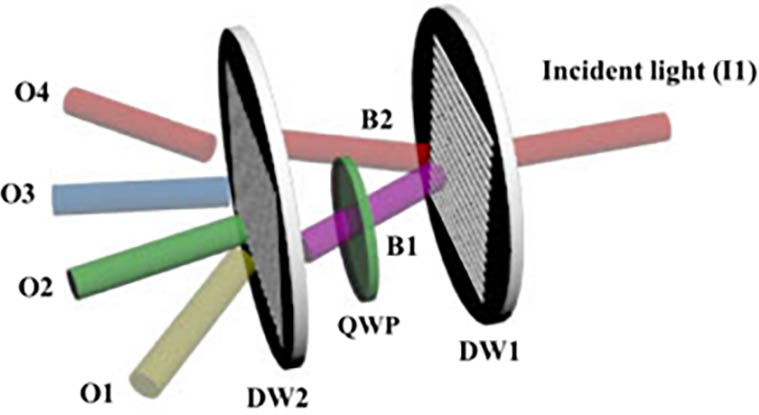
Fig. 1. Schematic of all-optical logic sequence generator. DW1 and DW2 are two different kinds of polarization holographic gratings. QWP is the quarter-wave plate. B1 and B2 represent the
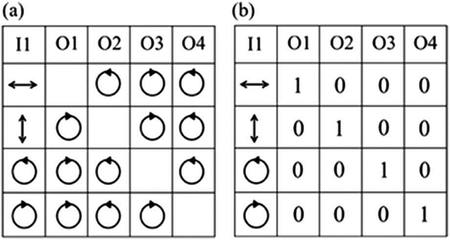
Fig. 2. (a) Diagram of the incident light signal of different polarization states and corresponding output light signals. (b) The logic sequence table. Column I1 represents four different polarizations of the incident light; columns O1, O2, O3, and O4 represent the diffraction light in four directions, respectively, corresponding to the yellow, green, blue, and red cylinders in Fig. 1 . Signal of output port denotes logic state 0; no signal denotes logic state 1.
Fig. 3. Diffraction patterns of (a) the DW1 grating and (b) the DW2 grating.
Fig. 4. Schematic diagram of working principle of all-optical logic sequence generator.
Fig. 5. Diagram of experimental optical path of photoinduced birefringence; P1 and P2 are two orthogonal polarizers.
Fig. 6. Curves of the intensity variation of transmitted light versus the duration of pump light. The black curve represents the intensity variation of transmitted light when pumping light is 18 mW and the red curve represents that of 30 mW.
Fig. 7. Schematic of the optical path for writing polarization gratings (a) DW1 and (b) DW2. BS, beam splitter; M1, M2, M3, mirror; HWP, half-wave plate; QWP, quarter-wave plate.
Fig. 8. (a) Diffraction of DW1 grating. (b) Diffraction of DW2 grating. S, P, Left, and Right represent four kinds of incident light, respectively. The three red dots from left to right in each row represent the
Fig. 9. Polarization states of incident light and diffraction light of DW1 and DW2. s-linearly polarized incident light and
Fig. 10. Schematic diagram of polarization modulation in orthogonal linearly polarized light interference field.
Fig. 11. Schematic diagram of polarization modulation in orthogonal circularly polarized light interference field.

Set citation alerts for the article
Please enter your email address
© Copyright 2018-2021 | Chinese Laser Press. All Rights Reserved 沪ICP备15018463号-20