State Key Laboratory of Advanced Optical Communication Systems and Networks, School of Physics and Astronomy, Shanghai Jiao Tong University, Shanghai 200240, China
In this Letter, an all-optical logic sequence generator based on two different polarization holographic gratings has been proposed and demonstrated, which has one input port and four output ports. The polarization state of input light signal determines logic output signals. It can produce four kinds of logic sequence output signals: 1000, 0100, 0010, and 0001, corresponding to the input light signal of four different polarization states: the p-linear, s-linear, left-handed circular, and right-handed circular. The two polarization gratings have been fabricated, and the working principle of the logic sequence generator has been proved by diffraction pattern analysis of polarization gratings.
Polarization holography has attracted much attention in recent research[1–3]. As a photosensitive material, azo material has great applications in recording polarization holography due to its unique optical properties[4–7]; many studies on the diffraction efficiency and selectivity of azo material have been carried out[8,9]. The azo liquid crystal polymer film can produce photoinduced birefringence under the irradiation of pump light. Because the photoinduced birefringence of azo liquid crystal polymer material is relatively stable, it is usually used as the substrate to fabricate polarization gratings by researchers[10–13]. As for polarization gratings, generally, the diffraction light of orders has been taken into account, and there is no diffraction light of other orders. Of course, in order to achieve this 100% diffraction efficiency, the thickness of the grating film , the optical anisotropy of material, and the wavelength of incident light should meet the half-wave condition[14]. Because of its diffraction characteristics, many applications based on polarization gratings have been developed, such as in the field of liquid crystal display[15].
In recent years, applications of optical communication devices in optical computing and other fields have found great progress[16,17]. A large number of methods have been adopted to achieve various optical logic operations[18,19]. These devices mainly utilize non-linear effects of optical materials or other physical principles. For example, a reconfigurable dual-channel all-optical logic gate in a silicon waveguide for polarization encoding signals by using four-wave mixing was proposed[20]. Theoretical research of the all-optical logic gates based on the techniques of cross phase modulation (XPM) in a phase-shifted grating was carried out by Li et al.[21]. Sobrinho et al. proposed the operation of an all-optical logical gate based on a symmetric non-linear directional coupler (NLDC) operating with pulse position modulation (PPM)[22].
In this Letter, we designed an all-optical logic sequence generator, which has one input port and four output ports, based on two different polarization holographic gratings. The logic signals of output ports depend entirely on the polarization of the input light signal. It can produce four kinds of logic sequence output signals: 1000, 0100, 0010, and 0001, corresponding to the input light signal of four different polarization states: the p-linear, s-linear, left-handed circular, and right-handed circular. There is no need for additional electronic control in this logic sequence generator, so it is very thin and can be easily integrated into various optical systems requiring optical signal control, such as optical path switching in an optical communication system.
Sign up for Chinese Optics Letters TOC. Get the latest issue of Chinese Optics Letters delivered right to you!Sign up now
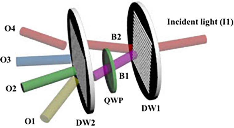
An all-optical logic sequence generator was designed, using a quarter-wave plate (QWP) of 633 nm and polarization holographic gratings DW1, DW2. The schematic diagram is shown in Fig. 1.
Figure 1.Schematic of all-optical logic sequence generator. DW1 and DW2 are two different kinds of polarization holographic gratings. QWP is the quarter-wave plate. B1 and B2 represent the and order diffraction light of DW1.
In Fig. 1, DW1 and DW2 are the gratings obtained by orthogonal linear and circular polarization light interference, respectively. In this structure, QWP is mainly used to convert 633 nm s-linearly polarized light into right-handed circularly polarized, p-linearly polarized light into left-handed circularly polarized, right-handed circularly polarized into p-linearly polarized, and left-handed circularly polarized into s-linearly polarized. The plane determined by the optical axis of incident light and the normal line of the grating is called the incident plane. p-linearly polarized light refers to linearly polarized light whose polarization direction is perpendicular to the incident plane. s-linearly polarized light refers to linearly polarized light whose polarization direction is parallel to the incident plane. The logic sequence generator will generate optical signals at different output ports when light with different polarization states is incident. This is shown in Fig. 2.
Figure 2.(a) Diagram of the incident light signal of different polarization states and corresponding output light signals. (b) The logic sequence table. Column I1 represents four different polarizations of the incident light; columns O1, O2, O3, and O4 represent the diffraction light in four directions, respectively, corresponding to the yellow, green, blue, and red cylinders in Fig. 1. Signal of output port denotes logic state 0; no signal denotes logic state 1.
In Fig. 2(a), when the incident light is p-linearly polarized, the diffraction light signals can be detected in the directions of 2, 3, and 4. When the incident light is s-linearly polarized, the diffraction light signals can be detected in the directions of 1, 3, and 4. When the incident light is left-handed circularly polarized, the diffraction light signals can be detected in the directions of 1, 2, and 4. When the incident light is right-handed circularly polarized, the diffraction light signals can be detected in the directions of 1, 2, and 3. If the signal of output port denotes logic state 0, no signal denotes logic state 1, so the logic sequence table can be obtained. In Fig. 2(b), the output of the p-linearly polarized incident light signal is logic sequence signal 1000, the output of s-linearly polarized incident light signal is logic sequence signal 0100, the output of left-handed circularly polarized incident light signal is logic sequence signal 0010, and the output of right-handed circularly polarized incident light signal is logic sequence signal 0001. The function of the device is mainly attributed to the diffraction characteristics of the gratings DW1 and DW2. Diffraction patterns of two polarization gratings DW1 and DW2 are shown in Figs. 3(a) and 3(b), respectively.
Figure 3.Diffraction patterns of (a) the DW1 grating and (b) the DW2 grating.
The DW1 grating was fabricated by orthogonal linearly polarized light interference. When the probe light is incident on polarization grating DW1, if the probe light is left-handed circularly polarized light, both the diffraction light of and orders is right-handed circularly polarized light. If the probe light is right-handed circularly polarized light, both the diffraction light of and orders is left-handed circularly polarized light. If the probe light is s-linearly polarized, both the diffraction light of and orders is p-linearly polarized. If the probe light is p-linearly polarized, both the diffraction light of and orders is s-linearly polarized. The DW2 grating was fabricated by orthogonal circular polarization light interference. If the probe light is left-handed circularly polarized, the polarization grating DW2 will only produce right-handed circularly polarized diffraction light of order, and no diffraction light of other orders. If the probe light is right-handed circularly polarized, the left-handed circularly polarized diffraction light of order will be produced, and no diffraction light of other orders. If the probe light is s-linearly polarized, order diffraction light is right-handed circularly polarized, and order diffraction light is left-handed circularly polarized. When the probe light is p-polarized, the diffraction pattern is the same as the former.
The schematic diagram of working principle of the all-optical logic sequence generator is shown in Fig. 4. Taking the incident light of p-linear polarization as an example, in Fig. 4(a), when the incident light is incident on the DW1, the orders diffraction light B1 and B2 are generated, and both of their polarization states are s-linear. Light B1 first passes through the QWP with its polarization state changing from s-linear to right-handed circular, and then is incident on the DW2. The diffraction light is generated in the direction of O2. Light B2 is directly incident on the DW2 and produces diffraction light in the direction of O3 and O4. That is to say, when the incident light is p-linearly polarized, only O2, O3, and O4 ports have optical signal output.
Figure 4.Schematic diagram of working principle of all-optical logic sequence generator.
Azo material is a kind of polarization sensitive material. If the pump light is linearly polarized, the azo molecules’ orientation will be perpendicular to the polarization direction of the pump light. Azo-doped liquid crystal polymer film is usually used to fabricate polarization gratings. Under the pump light, the photoisomerization of azo dyes occurs, and azo-doped liquid crystal polymer shows strong non-linear optical properties. In order to facilitate the fabrication of gratings, firstly, the real-time variation of its photoinduced birefringence was demonstrated by experiment. 532 nm laser was used as pumping light, and 633 nm laser was used as detecting light. The experimental optical path is shown in Fig. 5.
Figure 5.Diagram of experimental optical path of photoinduced birefringence; P1 and P2 are two orthogonal polarizers.
In Fig. 5, the angle between the polarization direction of P1 and the axis is 45°, while the polarization direction of P1 and P2 is orthogonal. In order to get an accurate light intensity curve, we used a lock-in amplifier to detect the intensity of transmitted light from P2. The result obtained from the lock-in amplifier is shown in Fig. 6.
Figure 6.Curves of the intensity variation of transmitted light versus the duration of pump light. The black curve represents the intensity variation of transmitted light when pumping light is 18 mW and the red curve represents that of 30 mW.
It can be seen that when the azo liquid crystal film is not illuminated by pumping light, the lock-in amplifier does not detect any transmitted light intensity signal, indicating that the azo material does not have birefringence characteristics at this time. When the pump light is turned on, the intensity of light detected by the lock-in amplifier increases continuously, indicating that under the action of pump light, the birefringence of azo liquid crystal material increases continuously. The intensity of transmitted light maintains its stability after reaching a maximum. When pump light is turned off, the intensity of transmitted light decreases slightly and tends to be stable, which indicates that the photoinduced birefringence of azo liquid crystal polymer material is relatively stable. Gratings DW1 and DW2 were fabricated by polarization holographic interference, respectively. Figures 7(a) and 7(b) are our experimental optical paths for fabricating DW1 and DW2 gratings.
Figure 7.Schematic of the optical path for writing polarization gratings (a) DW1 and (b) DW2. BS, beam splitter; M1, M2, M3, mirror; HWP, half-wave plate; QWP, quarter-wave plate.
In Fig. 7(a), the 532 nm laser was used as the pump light, whose initial polarization state is s-linear. We generated two beams of light through a beam splitter, one of which passed through a 532 nm half-wave plate so that it can be converted from s-linear polarization to p-linear polarization. The experimental optical path was adjusted to make the two beams have the same optical path. Finally, the two beams of light, whose polarization directions are orthogonal, interfered on the azo liquid crystal polymer film layer. In Fig. 7(b), the 532 nm laser was still used as the pump light, where two beams of light were generated through a beam splitter, one of which passed through a half-wave plate of 532 nm and a QWP of 532 nm, so that it could be converted from s-linear polarization to right-handed circular polarization; the other passed through a QWP of 532 nm, so that it could be converted from s-linear polarization to left-handed circular polarization. Finally, two beams of light interfered on the azo liquid crystal polymer film. The diffractions of gratings DW1 and DW2 are shown in Fig. 8.
Figure 8.(a) Diffraction of DW1 grating. (b) Diffraction of DW2 grating. S, P, Left, and Right represent four kinds of incident light, respectively. The three red dots from left to right in each row represent the , 0, order diffraction light.
The 633 nm laser was used as the probe light. In Fig. 8, four different polarized incident lights all have orders diffraction light. Because the thickness of the material film did not meet the half-wave condition of 633 nm, the diffraction light of zero order can also be observed. In fact, it is perfectly possible to make the zero order diffraction light disappear if the thickness of film can be precisely controlled to meet the half-wave condition: where is optical anisotropy of material film, and is the wavelength of the probe light. The polarization states of and order diffraction light of gratings under different polarized incident lights were detected with the polarization meter. The polarization states of the incident light and corresponding and order diffraction light of DW1 and DW2 are shown in Fig. 9.
Figure 9.Polarization states of incident light and diffraction light of DW1 and DW2. s-linearly polarized incident light and orders diffraction light of (a) DW1 and (e) DW2, p-linearly polarized incident light and orders diffraction light of (b) DW1 and (f) DW2, left-handed circularly polarized incident light and orders diffraction light of (c) DW1 and (g) DW2, right-handed circularly polarized incident light and orders diffraction light of (d) DW1 and (h) DW2.
The above experiment results can be demonstrated by the Jones matrix. As for DW1, the expressions of the polarization of 532 nm orthogonal linearly polarized light are and where means amplitude, and represents the phase difference between two orthogonal linearly polarized lights. The expression of the interference field is
The diagram of the polarization modulation of the interferential light field in the material film is shown in Fig. 10.
Figure 10.Schematic diagram of polarization modulation in orthogonal linearly polarized light interference field.
It is easy to obtain the orders diffraction transfer matrix of the polarization grating:
When the probe light is linearly polarized, the polarization states of orders diffraction light are the same. The light field of the orders diffraction light is
When the probe light is circularly polarized, the light field of the orders diffraction light is
When the detecting light is left-handed circularly polarized, , both the diffraction lights of and orders are right-handed circularly polarized. When the detecting light is right-handed circularly polarized, , both the diffraction lights of and orders are left-handed circularly polarized.
As for DW2, expressions of 532 nm orthogonal circularly polarized light are and The expression of the interference field is
The diagram of the polarization modulation of the interferential light field in the material film is shown in Fig. 11.
Figure 11.Schematic diagram of polarization modulation in orthogonal circularly polarized light interference field.
It is easy to obtain the orders diffraction transfer matrix of the polarization grating:
When the probe is linearly polarized, the light field of the orders diffraction light is
Whether the detecting light is s-linearly polarized or p-linearly polarized, the diffraction light is the same. When the probe light is circularly polarized, the light field of the orders diffraction light is
If the detecting light is left-handed circularly polarized, , the order diffraction light is right-handed circularly polarized, and there is no order diffraction light. If the detecting light is right-handed circularly polarized, , the order diffraction light is left-handed circularly polarized, and there is no order diffraction light.
In summary, an all-optical logic sequence generator based on two different polarization holographic gratings was proposed. The logic sequence generator can produce four different logic sequence signals by controlling the polarization state of the input signal light. In order to demonstrate the function of this device, the two polarization gratings were fabricated. Before fabrication of the gratings, the experiment of real-time variation of photoinduced birefringence of azo liquid crystal polymer materials was carried out. Furthermore, gratings DW1 and DW2 were fabricated by orthogonal linearly polarized light interference and orthogonal circularly polarized light interference, respectively. Their diffraction patterns and polarization states were proved by the Jones matrix theory. In order to reach the theoretical maximum value of diffraction efficiency, the thickness of the film needs to be precisely controlled to meet the half-wave condition. Because no additional electrical control is required, the device can be very thin and easily integrated into many optical communication systems requiring optical signal control, such as optical path switching in optical communication systems.
References
[1] P. Cai, J. Wang, C. Wang, P. Zeng, H. Li. Chin. Opt. Lett., 14(2016).