
Fengtao He, Yayi Yang, Jianlei Zhang, Yi Yang, Pengcheng Wei. Design of Underwater LED Omni-Directional Transmitting Antenna Based on Free-Form Surface[J]. Laser & Optoelectronics Progress, 2022, 59(1): 0106008
- Laser & Optoelectronics Progress
- Vol. 59, Issue 1, 0106008 (2022)
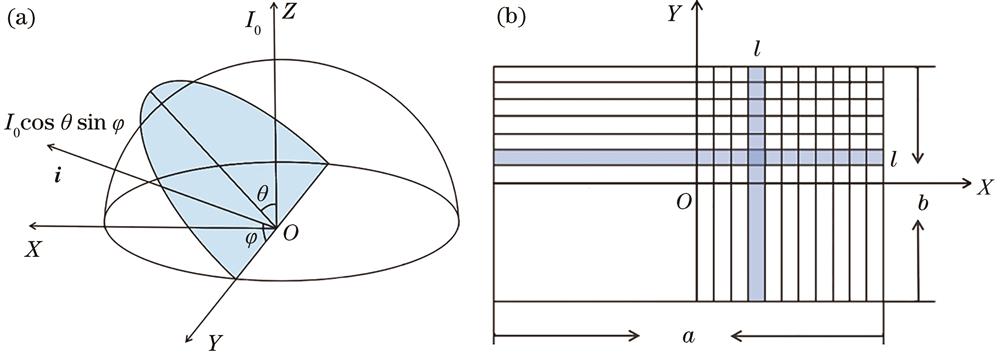
Fig. 1. Principle of the grid division. (a) Spatial coordinates of the LED light source; (b) grid division on the receiving surface
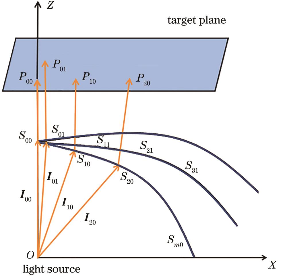
Fig. 2. Schematic diagram of the lens surface generation
Fig. 3. Free-form surface data of the uniform rectangular spot
Fig. 4. Solid model of the rectangular spot lens
Fig. 5. Irradiance distribution and profile of receiving surface. (a) Irradiance; (b) profile
Fig. 6. Simulation diagram of the underwater LED transmitting antenna experiment
Fig. 7. Light path diagram of the underwater LED transmitting antenna experiment
Fig. 8. Received optical power in different media
Fig. 9. Structure of the transmitting antenna. (a) Structure of the free-form surface lens; (b) structure of the omni-directional transmitting antenna
Fig. 10. Overall structure of the free-form surface lens
Fig. 11. Irradiance distribution and profile of single transmitting channel on the receiving surface 2. (a) Irradiance; (b) profile
Fig. 12. Irradiance distribution and profile of dual transmitting channel on the receiving surface 2. (a) Irradiance; (b) profile
Fig. 13. Irradiance distribution and profile on receiving surface 1. (a) Irradiance; (b) profile
Fig. 14. Irradiance distribution and profile on receiving surface 3. (a) Irradiance; (b) profile

Set citation alerts for the article
Please enter your email address
© Copyright 2018-2021 | Chinese Laser Press. All Rights Reserved 沪ICP备15018463号-20