• Chinese Optics Letters
  • Vol. 17, Issue 12, 123001 (2019)
Xiao Ma1、*, Jun Zou2, Wenhuan Li3, and Jian-Jun He1
Author Affiliations
  • 1College of Optical Science and Engineering, Zhejiang University, Hangzhou 310027, China
  • 2College of Science, Zhejiang University of Technology, Hangzhou 310023, China
  • 3Zhejiang Lightip Electronics Technology Co., Ltd., Wenzhou 325000, China
  • show less
    DOI: 10.3788/COL201917.123001 Cite this Article Set citation alerts
    Xiao Ma, Jun Zou, Wenhuan Li, Jian-Jun He. Miniature spectrometer based on a Fourier transform spectrometer chip and a commercial photodetector array[J]. Chinese Optics Letters, 2019, 17(12): 123001 Copy Citation Text show less
    Structure schematic of the miniaturized spectrometer. Three major parts including FTS chip, triplet lens, and linear CCD form the miniaturized spectrometer. In the FTS chip, the green box indicates the MZI array, and the yellow boxes indicate the Y-junction splitter and combiner. The two arms of each MZI have the same rotation angle but different radii as R1 and R2, leading to the OPD (optical path difference). The OPD in each MZI changes across the array along with the variation of the rotation angle.
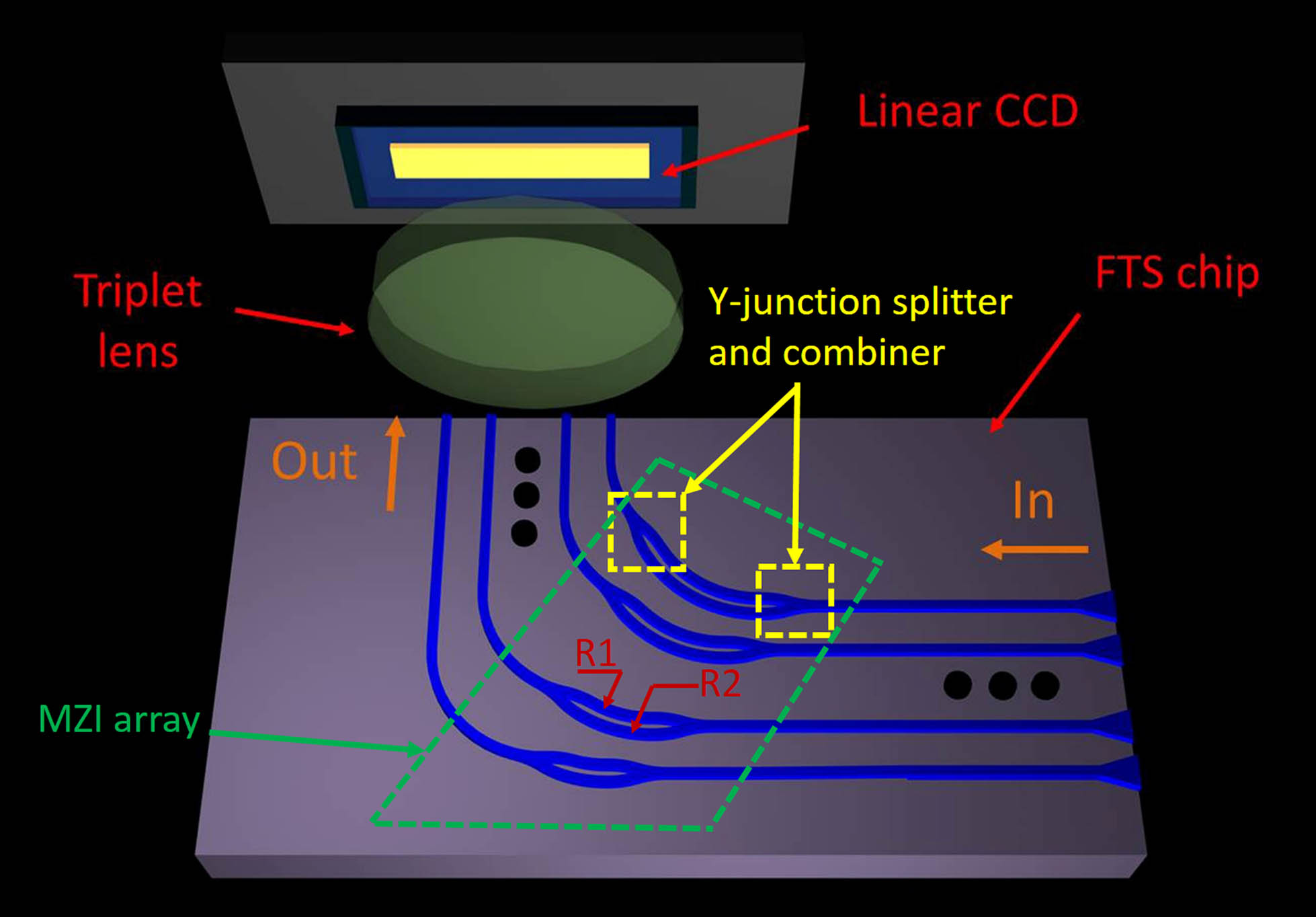
    Fig. 1. Structure schematic of the miniaturized spectrometer. Three major parts including FTS chip, triplet lens, and linear CCD form the miniaturized spectrometer. In the FTS chip, the green box indicates the MZI array, and the yellow boxes indicate the Y-junction splitter and combiner. The two arms of each MZI have the same rotation angle but different radii as R1 and R2, leading to the OPD (optical path difference). The OPD in each MZI changes across the array along with the variation of the rotation angle.
    Relation between the retrieved spectrum peak and the effective refractive index change.
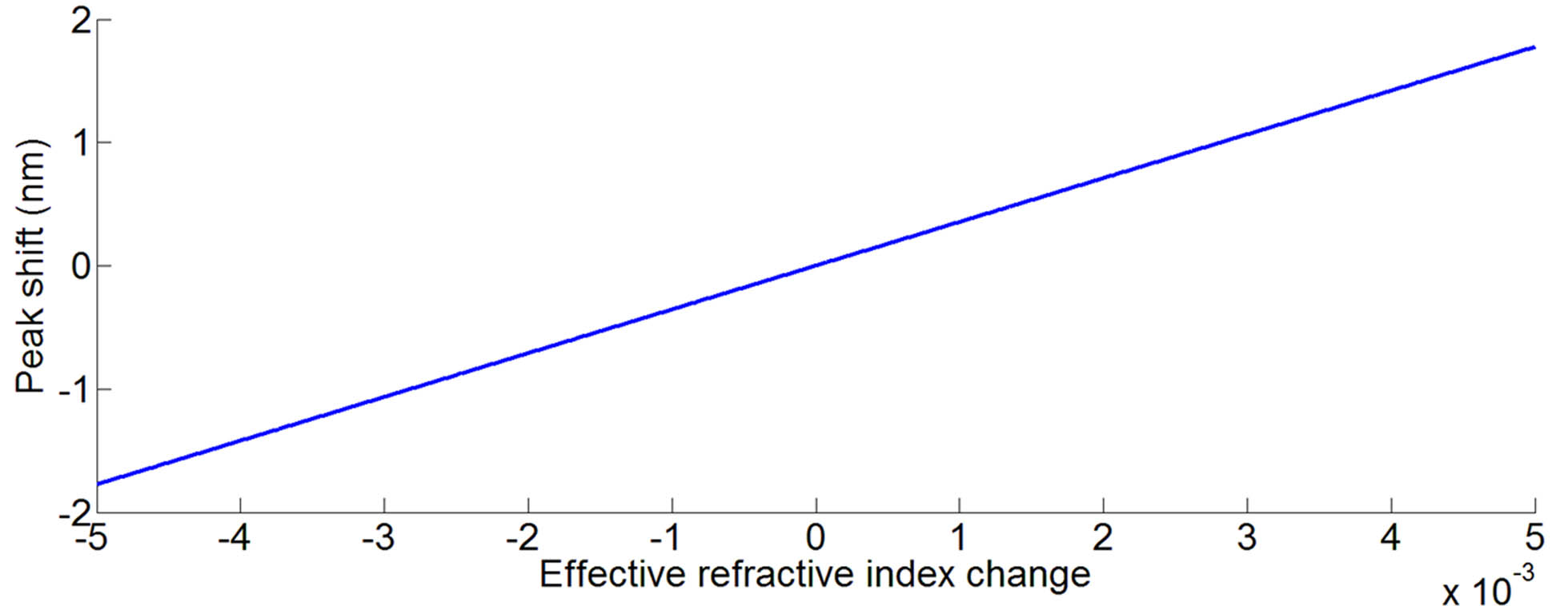
    Fig. 2. Relation between the retrieved spectrum peak and the effective refractive index change.
    (a) Photograph of our quartz-based FTS chip next to a quarter. (b) Micrograph of adjacent splitters in two MZIs; waveguides between them are accompanying waveguides used to improve fabrication, and no light transmits in them.
    Fig. 3. (a) Photograph of our quartz-based FTS chip next to a quarter. (b) Micrograph of adjacent splitters in two MZIs; waveguides between them are accompanying waveguides used to improve fabrication, and no light transmits in them.
    Normalized 2-D color scaling graph based on the transformation matrix T resulting from the entire measured transmission spectra of all the 51 MZIs from 460 nm to 510 nm.
    Fig. 4. Normalized 2-D color scaling graph based on the transformation matrix T resulting from the entire measured transmission spectra of all the 51 MZIs from 460 nm to 510 nm.
    Original and retrieved normalized spectra of the light emitted by a 532 nm laser.
    Fig. 5. Original and retrieved normalized spectra of the light emitted by a 532 nm laser.
    Spot diagrams when (a) the object height is 0 mm and the aperture angle is 7 deg at wavelengths of 0.48 μm, 0.55 μm, and 0.78 μm; (b) the object height is 0.5 mm and the aperture angle is 7 deg at wavelengths of 0.48 μm, 0.55 μm, and 0.78 μm. The unit of the scaleplate is μm.
    Fig. 6. Spot diagrams when (a) the object height is 0 mm and the aperture angle is 7 deg at wavelengths of 0.48 μm, 0.55 μm, and 0.78 μm; (b) the object height is 0.5 mm and the aperture angle is 7 deg at wavelengths of 0.48 μm, 0.55 μm, and 0.78 μm. The unit of the scaleplate is μm.
    Photograph of the mounted miniature spectrometer with the FTS chip, triplet lens, linear CCD, and a controlling electric circuit board.
    Fig. 7. Photograph of the mounted miniature spectrometer with the FTS chip, triplet lens, linear CCD, and a controlling electric circuit board.
    CCD readout when 532 nm lasing light illuminates the input plane of the FTS chip. When no light enters the sensing element, the CCD readout is around 2640. The smaller the readout number is, the larger the optical power is. The red number in the figure marks the related MZI in the chip.
    Fig. 8. CCD readout when 532 nm lasing light illuminates the input plane of the FTS chip. When no light enters the sensing element, the CCD readout is around 2640. The smaller the readout number is, the larger the optical power is. The red number in the figure marks the related MZI in the chip.
    Original and retrieved spectra of 532 nm lasing light.
    Fig. 9. Original and retrieved spectra of 532 nm lasing light.
    ParametersOur spectrometerC12666MA
    Spectral range (nm)489–584340–780
    Resolution (nm)415
    Ratio of spectral range to resolution2429
    Size (mm)45 × 20 × 1220 × 13 × 10
    Wavelength reproducibility (nm)<0.1nm<0.5nm
    Wavelength temperature dependence (nm/K)0.0030.1
    Input aperture (μm)714 × 2750 × 50
    NA0.04 (horizontal) 0.17 (vertical)0.22
    Table 1. Performance Comparison between Our Miniature Spectrometer and Hamamatsu C12666MA
    Xiao Ma, Jun Zou, Wenhuan Li, Jian-Jun He. Miniature spectrometer based on a Fourier transform spectrometer chip and a commercial photodetector array[J]. Chinese Optics Letters, 2019, 17(12): 123001
    Download Citation