
Yanlu Wang, Zhiping Yang, Mingyu Li, Jian-Jun He, Qiushun Li, "Thermal-optic tuning cascaded double ring optical sensor based on wavelength interrogation," Chin. Opt. Lett. 20, 011301 (2022)
- Chinese Optics Letters
- Vol. 20, Issue 1, 011301 (2022)
Abstract
1. Introduction
The integrated optical waveguide sensor based on silicon on insulator (SOI) material has the advantages of high refractive index (RI) contrast, compatibility with complementary metal oxide semiconductor (CMOS) technology, and large thermo-optical coefficient of
Micro-ring resonators are widely used in optical filters[
In this paper, the reference ring of the cascaded double-ring resonator (CDRR) sensor with a micro-heater and a microfluid control system for sensing by converting the wavelength shift into the electrical power change is investigated. The RI sensitivity will not change over the different temperatures. The RI change of the sample in the sensing ring results in the envelope peak shift of the CDRR sensor. When the temperature of the reference ring is controlled by adjusting the electric power of the micro-heater, the envelope peak of the CDRR sensor can move back to the initial position. When the RI of the measured sample is changed, the envelope of the sensor’s transmission spectrum can be retrieved within an 8 nm wavelength measurement range by changing the electrode power of the micro-heater. A large-bandwidth spectrometer or a large wavelength range tunable laser is not required, which reduces the cost of the sensing system. The experimental results show that the sensitivity is 33.703 W/RIU.
Sign up for Chinese Optics Letters TOC. Get the latest issue of Chinese Optics Letters delivered right to you!Sign up now
2. Theoretical Analysis
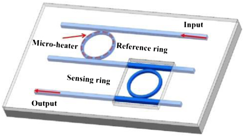
The schematic diagram of the CDRR sensor is shown in Fig. 1. The sensor is composed of a reference ring with a micro-heater and a sensing ring from removing the up-cladding layer. The transmission of the through port for reference ring is[
![]()
Figure 1.Cascaded double-ring resonator sensor schematic.
The transmission spectrum of the sensing ring Ts and the transmission spectrum of the reference ring Tr have the same form, and the total transmission of the CDRR is
When light is transmitted in a waveguide, the proportion of the evanescent wave field in the entire mode field distribution has a greater impact on the sensing performance of the device. The device adopts a strip waveguide structure, which supports the transverse electric (TE) mode and transverse magnetic (TM) mode of the two polarization modes, where the difference is that most of the energy of the TE mode electric field is in the
![]()
Figure 2.Mode profiles in the Si waveguide (
The radii of the reference ring and the sensing ring are different, causing the Tr and Ts free spectral ranges (FSRs) to be unequal, as shown in Fig. 3(a). The sensor transmission spectrum envelopes change with the RI of the sample, and the electric power variations of the micro-heater are shown in Fig. 3(b). The operating principle of the thermo-optical effect sensing system is that when the RI of the measured sample changes
![]()
Figure 3.Principle of thermo-optical tuning.
When Fig. 3(b) overlaps with Fig. 3(f), the electrical power of the micro-heater for the retrieved spectrum envelope is determined, and the sensitivity of the sensor can be expressed as
The shift of the transmission spectrum envelope is
It can be seen from Eq. (5) that the detection limitation is related to the accuracy of the current source voltage. Thus, the sensitivity and detection limitation can be improved by a high-precision electrical source.
3. Experiment
The sensing chip was based on an 8 inch (1 inch = 2.54 cm). SOI wafer with 220-nm-thick top Si layer and 2-µm-thick buried oxide layer. The whole fabrication process compatible with the CMOS process was completed in the Integrated Circuit Advanced Process Center (ICAC) of the Institute of Microelectronics of Chinese Academy of Science (IMECAS), Beijing, China. The patterns of the waveguides, grating couplers, and micro-rings were formed by the stepper and inductively coupled plasma (ICP) etching, then by growing 2 µm
![]()
Figure 4.(a) Photograph of the chip. (b) Optical microscope image of the CDRR. (c) SEM image of the sensing ring. (d) Photograph of the microfluidic control system.
Figure 5 is the schematic of testing the CDRR sensor system. The tunable laser (Keysight 81606B) was controlled by Keysight Photonic Suite N7700. The laser was coupled into and out of the sensor chip by the grating couplers and was finally detected by an optical power meter (Agilent 81634 A). A personal computer (PC)-controlled current source (KEITHLEY 2400) is used to add electrical power on the micro-heater of the reference ring. The NaCl solution with different concentration was pumped into the sensing ring through the microfluidic channel. The transmission spectral envelopes for the different concentrations of NaCl solution were fitted[
![]()
Figure 5.Experimental device diagram.
4. Results and Discussion
When the RI of the cladding on the sensing ring changes, the envelope of the transmission spectrum of the cascaded double ring will shift. The radii of the reference ring and the sensing ring of the cascaded double-ring sensor are 123 µm and 121 µm, respectively. When the RI of the sample increased, the transmission spectrum envelope of the cascaded double-ring sensor shifted to the short wavelength. Figure 6 showed the transmission spectra of the CDRR with the NaCl concentrations of 1.0% and 1.4%. The envelope shift of the transmission spectrum can be measured by the Gaussian function fitting in the wavelength range of 8 nm. The difference between 1.0% and 1.4% of the solution concentration resulted in a blue envelope peak shift of 2.85 nm, as shown in Fig. 6.
![]()
Figure 6.Transmission spectra of drop port with 1.0% NaCl solution and 1.4% NaCl solution.
By using different concentrations (1.0%, 1.1%, 1.2%, 1.3%, 1.4%, and 1.5%) of NaCl solution, the RI sensitivity without a thermal-optical tuning CDRR sensor was calibrated. For every 1% change in concentration, the RI changes
![]()
Figure 7.Wavelength shift versus the RI change.
The resistance of the micro-heater was above 1.8 kΩ, as shown in Fig. 8, by fitting the curve of voltage versus electrical power.
![]()
Figure 8.Peak-to-valley (P-V) curve of the micro-heater.
The transmission spectra of the reference ring through the port and the CDRR with the different electrical powers (0 mW, 22.8 mW, 50.3 mW, 88.12 mW, and 136.15 mW) are shown in Figs. 9(a) and 9(b), respectively. With the electric power increasing, the envelope peak results in a spectral red-shift in Fig. 9(b). The measured shift of the single-ring resonant wavelength and the CDRR transmission spectrum envelope peak as a function of the electrical power are shown in Figs. 9(c) and 9(d), respectively. According to the linear fitting, the thermal tuning coefficients of the single-ring and CDRR were 0.006 nm/mW and 0.121 nm/mW, respectively. The results showed that the Vernier effect increased the thermal tuning coefficient by 20 times.
![]()
Figure 9.Comparison of thermal tuning coefficients of single ring and double ring.
The sensitivity of the CDRR with the micro-heater for the thermal-optical tuning was measured in Fig. 10. The spectrum for the NaCl concentration of 1.0% is the initial spectrum. For the NaCl solutions of different concentrations (1.1%, 1.2%, 1.3%, 1.4%, and 1.5%), the output spectrum envelope was retrieved into the initial spectrum by changing the electric power of the micro-heater. The transmission spectrum was fitted by Gaussian function only in the 8 nm wavelength range.
![]()
Figure 10.(a) Retrieved spectra for 1.2% concentration of NaCl solution. (b) The linear fit curve of the thermo-optical tuning sensing sensitivity.
The linear fitting relationship between the retrieved electrical power and the RI change is shown in Fig. 10(b). The thermo-optical tuning sensitivity of the CDRR is 33.703 W/RIU. The limit of detection (LOD) can be expressed as
5. Conclusion
An optical sensing system based on the thermo-optical effect of CDRR is proposed in this paper. The sensing system included a sensing ring and a reference ring with a micro-heater for thermo-optical tuning. The retrieved electrical power was measured for sensing the RI change of the sample. The sensing system did not require a broad bandwidth spectrometer or a large range wavelength tunable laser. The envelopes of the transmission spectra were retrieved by fitting the Gauss function in the 8 nm wavelength range. The sensitivity for the TM mode was 33.703 W/RIU, and the LOD was
References
[1] L. Qing, W. K. Kyung, K. Jack, J. Song, K. P. Mi. Thermal characterization of electrical tracing-assisted dual-microring optical sensors. Opt. Express, 22, 27069(2014).
[2] J. Song, X. Luo, S. K. Jack, H. Kyung, C. Li, K. P. Mi, X. Tu, X. Zhang, Q. Fang, L. Jia, J. Y. Yong, Y. L. Tsung, M. Yu, G. Luo. Silicon-based optoelectronic integrated circuit for label-free bio/chemical sensor. Opt. Express, 21, 17931(2013).
[3] J. Song, X. Tu, M. K. Park, J. S. Kee, H. Zhang, M. Yu, G. Luo, D. L. Kwong. Electrical tracing assisted dual microring label free optical bio/chemical sensors. Opt. Express, 20, 4189(2012).
[4] R. P. Prashanth, K. S. Shankar, M. V. Manoj. Full-range detection in cascaded microring sensors using thermooptical tuning. J. Lightwave Technol., 34, 5157(2016).
[5] G.-D. Kim, H.-S. Lee, C.-H. Park, S.-S. Lee, B. T. Lim, H. K. Bae, W.-G. Lee. Silicon photonic temperature sensor employing a ring resonator manufactured using a standard CMOS process. Opt. Express, 18, 22215(2010).
[6] S. Li, R. Cong, Z. He, T. Wang, F. Zhang, S. Pan. Switchable microwave photonic filter using a phase modulator and a silicon-on-insulator micro-ring resonator. Chin. Opt. Lett., 18, 052501(2020).
[7] Y.-P. Qi, X.-W. Zhang, P.-Y. Zhou, B.-B. Hu, X.-X. Wang. Refractive index sensor and filter of metal-insulator-metal waveguide based on ring resonator embedded by cross structure. Acta Phys. Sin., 67, 197301(2018).
[8] X.-W. Dong, L. Pei, S.-S. Jian. Transfer matrix method for analyzing the characteristics of multiple-ring higher order microring resonators. Chin. J. Lasers, 32, 929(2005).
[9] F. Meng, H. Yu, X. Zhou, Y. Li, M. Wang, W. Yang, W. Chen, Y. Zhang, J. Pan. Quantum wells micro-ring resonator laser emitting at 1746 nm for gas sensing. Chin. Opt. Lett., 19, 041406(2021).
[10] F. Y. Meng, H. Y. Yu, X. L. Zhou, Y. J. Li, M. Q. Wang, W. Y. Yang, W. X. Chen, Y. J. Zhang, J. Q. Pan. Quantum wells micro-ring resonator laser emitting at 1746 nm for gas sensing. Chin. Opt. Lett., 19, 041406(2021).
[11] W.-Y. Deng, S.-L. E, C.-S. Ma, H.-D. Zhao, W. Xu. Multi channel access micro ring resonator wavelength selective switching characteristics. Acta Photon. Sin., 37, 2394(2008).
[12] X. Tong, K. Han, X.-P. Shen, Q.-H. Wu, F. Zhou, Y. Ge, X.-J. Hu. Equal intensity polarization-independent beam splitter based on photonic crystal self-collimation ring resonator. Acta Phys. Sin., 60, 064217(2011).
[13] M. You, Z. Lin, X. Li, J. Liu. Chip-scale silicon ring resonators for cryogenic temperature sensing. J. Lightwave Technol., 38, 5768(2020).
[14] J. Song, X. Luo, X. Tu, K. P. Mi, S. K. Jack, H. Zhang, M. Yu, G. Luo, D. L. Kwong. Electrical tracing-assisted dual-microring label-free optical bio/chemical sensors. Opt. Express, 20, 4189(2012).
[15] Y. Liu, Y. Li, M. Li, J. J. He. High-sensitivity and wide-range optical sensor based on three cascaded ring resonators. Opt. Express, 25, 972(2017).
[16] Y. Zhang, J. Zou, Z. Cao, J. J. He. Temperature insensitive waveguide sensor using a ring cascaded with a Mach Zehnder interferometer. Opt. Lett., 44, 299(2019).
[17] Y. Yue, H. Zhu, Z. Cao, J. He, M. Li. Wide-range optical sensors based on a single ring resonator with polarization multiplexing. Chin. Opt. Lett., 17, 031301(2019).
[18] X. Jiang, L. Tang, J. Song, M. Li, J.-J. He. Optical waveguide biosensor based on cascaded Mach–Zehnder interferometer and ring resonator with Vernier effect. Proc. SPIE, 9310, 931003(2015).
[19] L. Jin, M. Li, J. J. He. Highly sensitive silicon on insulator sensor based on two cascaded micro ring resonators with Vernier effect. Opt. Commun., 284, 156(2011).
[20] C. Su, H.-H. Zhu, Z.-W. Cao, J.-J. He, M.-Y. Li. Fitting methods of transmission spectrum envelope in cascaded double-ring resonator sensors. Acta Photon. Sin., 47, 1023002(2018).


Set citation alerts for the article
Please enter your email address

© Copyright 2018-2021 | Chinese Laser Press. All Rights Reserved 沪ICP备15018463号-20