
Zhuqiang Zhong, Da Chang, Wei Jin, Min Won Lee, Anbang Wang, Shan Jiang, Jiaxiang He, Jianming Tang, Yanhua Hong. Intermittent dynamical state switching in discrete-mode semiconductor lasers subject to optical feedback[J]. Photonics Research, 2021, 9(7): 1336
- Photonics Research
- Vol. 9, Issue 7, 1336 (2021)
Abstract
1. INTRODUCTION
In nonlinear systems, the folding and stretching behaviors of variables result in different dynamical route to chaos [1]. Typically, period-doubling bifurcation and quasi-periodic bifurcation are mostly observed and have been investigated in detail [2,3]. Besides, intermittent bifurcation is another important route to chaos, which is characterized as the erratic switching between laminar and turbulent phases and has been widely observed in fluid flows, stirred chemical reactions, and economics [4–6]. Moreover, intermittency has also been observed in various classes of lasers such as solid-state lasers [7], gas lasers [8], and semiconductor lasers (SLs) [9–11]. For SLs, external perturbations are usually required to drive the SL into chaos, which generally include optical feedback, optical injection, optoelectronic feedback, or modulation [12–14]. Among these perturbations, optical feedback is commonly adopted because of the simplicity and high dimensionality [15–17]. Therefore, the intermittent phenomenon in external cavity optical feedback (ECF) SLs has attracted significant research interests.
Low-frequency fluctuations (LFFs) are first observed and considered as intermittency in ECF-SLs. The corresponding output of ECF-SL exhibits a sudden power dropout and then recoveries gradually with a frequency of (MHz), which is much lower than the relaxation oscillation frequency [18], and the physical mechanism is considered as the unstable saddle-node and intermittent instability involved in ECF-SLs [19]. Different from LFFs, some intermittent phenomena have also been observed and studied in a short () external cavity SL [20–22]. Bosco
As a special type of Fabry–Pérot (FP) SLs, discrete-mode (DM) SLs, in which the refractive index of very small sections is modified by etching features into the ridge waveguide and suitable positioning of these interfaces along the laser cavity, achieve single longitudinal mode operating with high side-mode suppression [27]. DM lasers can be used in coherent communication, optical sensing, and terahertz wave generation resulting from their unique characteristics including very narrow linewidth emission, wide temperature range of operation, low cost, and easy integration [28,29]. Although a DM-SL is less sensitive to external perturbations because of its special design of the intercavity structure, we recently experimentally generated a flat broadband chaos output from a DM-SL with amplified optical feedback [30]. However, the detailed dynamics in routes to chaos of the DM laser are scarce.
Sign up for Photonics Research TOC. Get the latest issue of Photonics Research delivered right to you!Sign up now
In this paper, the intermittent dynamical state switching in a long ECF DM-SL is experimentally and numerically investigated. In the experiment demonstration, the dynamical route to chaos as well as the dynamics distribution in the parameter space of feedback ratio and bias current has been examined. The duty cycle for the bursting phases is introduced to quantitatively explore the dynamical switching between stable state and period-one oscillations with a square-wave envelope. In the simulation, the Lang–Kobayashi rate equations are adopted to model the long ECF DM-SL. The simulation results agree qualitatively with the experimental observations. The rest of this paper is organized as follows. Section 2 describes the experiment setup of long ECF DM-SL. Section 3 analyzes the observed regular and irregular dynamics switching in detail. The theoretical model and simulation results are provided and discussed in Section 4. Conclusions are drawn in Section 5.
2. EXPERIMENTAL SETUP
The schematic diagram of the experimental setup is illustrated in Fig. 1. A commercially available TO-56 can-packaged DM laser (EP1550-DM-01-FA) provided by Eblana Photonics with a lasing wavelength of is used in this experiment. The bias current is supplied by an ultralow noise current source. The temperature of the DM-SL is set at 24.85°C with an accuracy of 0.01°C, and the threshold current of the solitary DM-SL at this temperature is 12.0 mA. Light emitted from the DM-SL first passes through an optical circulator (OC) and then travels through a 50/50 fiber coupler (), and the light is divided into two paths. One path is used to form an optical feedback loop, which contains an erbium-doped fiber amplifier (EDFA), a polarization controller (PC), a variable optical attenuator (VA), and another fiber coupler (). The polarization of the feedback light is adjusted by the PC to match the emission of the laser, and the VA is used to tune the feedback ratio . The feedback ratio is defined as the ratio of the feedback power to the solitary laser output power, and the feedback power is extracted from a power meter (PM) reading after taking into account the split ratio of and the loss of the optical circulator. The other path of is sent to the detection part, where the light is further split to be detected by a 25 GHz photodetector (, New Focus 1414) and a 12 GHz photodetector (, New Focus 1544-B). After optical to electrical conversion, the time series and electrical spectra of the output of DM-SL are recorded by an electrical spectrum analyzer (ESA, Anritsu MS2667C, 30 GHz bandwidth) and a digital oscilloscope with a sampling rate of 50 GS/s (OSC, Tektronix 71254C, 12.5 GHz bandwidth). In the experiment, the optical feedback round-trip time is 216.1 ns.
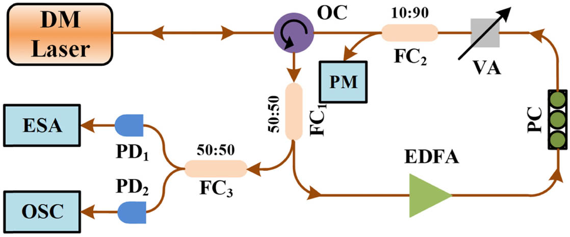
Figure 1.Experimental setup. DM Laser, discrete-mode laser; OC, optical circulator; FC, fiber coupler; EDFA, erbium-doped fiber amplifier; PC, polarization controller; VA, variable optical attenuator; PM, power meter; PD, photodetector; ESA, electrical spectrum analyzer; OSC, oscilloscope.
3. EXPERIMENTAL RESULTS
The dynamical route to chaos of the ECF DM-SL is firstly examined. Figure 2 illustrates the time series and power spectra under different feedback ratio at the bias current of 40 mA. Noise floor in the power spectra is presented with grey line in Figs. 2(b1)–2(b3). For (row 1), the power spectrum shows a sharp peak at , which is close to the relaxation oscillation frequency when the DM-SL operates at 40 mA. However, in Fig. 2(a1), the time series exhibits a stable state, at the time window from 0 ns to . Therefore, this dynamical state is assessed as switching between stable state () and period-one state (P1). As plotted in Fig. 2(a2), the output time series obtained with shows a varying amplitude modulated by a square-wave like envelope. In Fig. 2(b2), the fundamental frequency peak at is broadened with some sideband peaks, and the powers at lower frequencies also increase. Thus, this dynamic can be viewed switching between stable state and quasi-periodicity (QP). Further increase to 0.300 (row 3), the time series becomes dramatically noise-like fluctuation and the power spectrum becomes flatten and smooth, which indicates chaos achieved by optical feedback. From the above experimental observations, we find a quasi-period route to chaos in the ECF DM-SL when increasing . Different from the quasi-period route in other ECF-SLs [31], a regular intermittent switching between and P1 with a square-wave envelope is observed within a certain range of . This interesting phenomenon will be described in detail below.
![]()
Figure 2.Time series and power spectra of the ECF DM-SL output intensity when bias current is 40 mA, where the feedback ratio
![]()
Figure 3.(a) Time series, (b) power spectra, and (c) phase portraits of the output of ECF DM-SL when
In Fig. 3, the first column shows the time series recorded by the oscilloscope. The inset figures present zoomed-in details when dynamical state switching occurs within 3 ns span. The second column shows the corresponding power spectra, and the third column presents the phase portraits, which are defined as the local th intensity as a function of ()th intensity. Obviously, from time series, power spectra, and phase portraits, we could conclude a regular switching involved the alteration between and P1. It should be pointed out that the regularity refers to the bursting phases that are separated by regular laminar time intervals. The phase portraits show two attractors. One cluster sited around (3.2 mV, 3.2 mV) is S with noise fluctuation, and the circle around to 40 mV represents P1 oscillation. In addition, the repeat periods have a close relationship with the optical feedback round trip time . As shown in Fig. 3(a1), for , the time series of the ECF DM-SL’s output shows a nearly constant lasting from to . Then from to , the dynamics of the laser switches to P1 state. The switching between and P1 repeats every with a duty cycle of 0.17. Here the duty cycle is defined as the duration of the P1 state over a feedback round-trip time . For , the dynamics shown in Fig. 3(a2) still has a switching between and P1, but the duration of increases. As a result, the duty cycle reduces to . As increases to 0.059, the dynamics switching in Fig. 3(a3) is triggered 3 times within a feedback round-trip time, and the duty cycle increases to 0.22. Further increasing to 0.063, the dynamics switching occurs 4 times within a as shown in Fig. 3(a4). However, the duration of P1 within a feedback round-trip time decreases, so the duty cycle of P1 reduces to 0.18.
![]()
Figure 4.Duty cycle of the periodic oscillation as a function of
The duty cycle of the bursting phases as a function of at the bias current of 40 mA is summarized in Fig. 4, in which the points A, B, C, and D correspond to the in Fig. 3. For , the dynamical state of the ECF DM-SL remains at a stable state, and thus the duty cycle is 0 (not shown in Fig. 4). With the increase of from 0.040 to 0.048, the duty cycle increases monotonically with the increase of the feedback ratio until the duty cycle reaches 0.17 at the feedback ratio of 0.048. With further increase of from 0.049 to 0.051, the duty cycle drops gradually to 0.1. Continuing to increase the feedback ratio to 0.056, the duty cycle increases again. Carry on increasing the feedback ratio, the duty cycle decreases and then increases immediately. But one dynamics switching within a feedback round-trip time changes to three switches at as displayed in Fig. 3(a3). Further increase from 0.059 to 0.062, the duty cycle decreases from 0.22 to 0.16. When , three-times switches between and P1 within a suddenly change to four-times switches. When , the duration of the becomes very short, and the dynamic is about to leave the regular dynamical switching region. Compared with the previously reported intermittency in DFB lasers [25], regular multi-switches between and P1 within a feedback round-trip time during the dynamical route to chaos is observed for the first time in DM-SLs, and such regular multiple switches may result from the intercavity structure of DM-SLs [27–30] as well as the long ECF-induced instability. The further explorations are currently being undertaken in our research laboratory, and corresponding results will be reported elsewhere in due course.
Apart from the regular dynamical switching between and P1, the irregular intermittent dynamical switching between and quasi-period (QP), and multi-states, as well as and chaos is also observed at higher bias current. Figure 5 depicts the time series, their corresponding power spectra, and their phase portraits when . For (row 1), the time series looks similar to that in Fig. 3(a1), containing a stable state () and a square-wave-like envelope bursting phase region within a feedback round-trip time. However, the zoom-in of the bursting phase regions, shown in the inset of Fig. 5(a1), presents a slow varied intensity modulation characteristic. In addition, the slow varied intensity modulation is separated by small random time intervals of laminar phase, which is different from the regular dynamics switching between and P1 in Fig. 3, and we name it irregular intermittent dynamics switching. From the phase portrait [Fig. 5(c1)], the attractor shows an attractor-merging crisis [24]. Therefore, the dynamics are governed by the switching between and QP. For (row 2), the duration of the bursting phase regions is different. The inset of Fig. 5(a2) also manifests stable-state, period-two oscillation (P2), and QP. Figure 5(b2) also exhibits a sharp frequency peak at and two broad frequency peaks at and . There are many side peaks near the 10.2 GHz peak, which are caused by the external cavity mode. Moreover, the phase portrait in Fig. 5(c2) exhibits a trajectory cross among these attractors. The stable attractor is tangent to the P1 orbit. The P1 and P2 orbits are crossed at two fixed points, and the crisis leads to an abrupt change in the optical intensity range. Here we name it intermittent dynamics switching between and multi-states. When increases to 0.204, the time series shows erratic fluctuation behavior, and the periodicity related to the feedback round-trip time can hardly be identified. When zooming in on the time series, very short periods of stable states can be seen, usually lasting a few nanoseconds between the chaotic oscillations. Combining the power spectrum and the phase portrait, the dynamics are assessed to be the intermittent switching between and chaos.
![]()
Figure 5.(a) Time series, (b) power spectra, and (c) phase portraits for the output of the DM-SL when
The above results reveal that the dynamical behaviors of the ECF DM-SL are strongly related to the feedback ratio and bias current. A two-dimensional map of dynamical states of the ECF DM-SL in the parameter space of and is plotted in Fig. 6. The bias current varies from 30 mA to 70 mA with 10 mA interval, and the feedback ratio is varied from 0 to 0.3. The different dynamical states are represented by different color blocks. In Fig. 6, we can see that a larger feedback ratio is needed to trigger the ECF DM-SL into chaos for a higher bias current, which agrees with the results in Ref. [32]. When , the dynamical switching only involves and P1 in a narrow feedback ratio ranging from 0.01 to 0.03. When the feedback ratio is above 0.03, the laser operates at a QP or chaos dynamic, and no dynamical switching is observed. When or 50 mA, in addition to and P1 switching, another dynamic, namely, and QP switching, emerges, which occurs when the feedback ratio is around 0.07. When the DM-SL operates at 60 mA, the intermittency between and multi-states is observed within the feedback ratio range from 0.12 to 0.15. When the bias current of the laser is 70 mA, the ECF DM-SL directly enters the intermittent dynamics of S and QP at of , without the regular dynamical switching between and P1. The intermittent dynamics between and chaos have been observed at the feedback ratio from 0.19 to 0.25 before the laser enters the fully developed chaos.
![]()
Figure 6.Mapping of dynamical states of the ECF DM-SL in the parameter space of
4. THEORETICAL MODEL AND RESULTS
To understand the dynamical switching, the Lang–Kobayashi model [33] is deployed to simulate the dynamics of the discrete-mode semiconductor lasers with long ECF, which are described as
Figure 7 presents the time series, the corresponding power spectra, and the phase portraits when . For and , the time trace of laser output in Fig. 7(a1) shows from to , then switches to P1 dynamic from to , and repeats in every . According to the aforementioned definition of duty cycle, the duty cycle is 0.83. When increases to as shown in row 2 of Fig. 7, three bursting phases with P1 separated by stable states can be found from the time series trace of Fig. 7(a2). The duty cycle increases to 0.88. The power spectra in Figs. 7(b1) and 7(b2) show that the fundamental frequency is located at with some sidebands, which result from the P1 dynamic modulated by a square-wave envelope. From Figs. 7(c1) and 7(c2), we can clearly see a closed loop and orbits from the loop to the stable fixed point. All the evidences above verify a regular switching between S and P1, which qualitatively agrees with our experimental observations.
![]()
Figure 7.(a) Time series, (b) power spectra, and (c) phase portraits for the output of the DM-SL when
The relationship between the duty cycle and the number of regular dynamical switching between and P1 has been theoretically studied. Figure 8 shows the duty cycle as a function of . is kept at , and . For , the duty cycle almost monotonically increases from 0.53 to 0.83, and the dynamics switching between and P1 occurs only once. When , a one-time switch between and P1 within a transits to two-times switches, and duty cycle increases to 0.87. During the upswing of from to , the duty cycle decreases slightly to 0.84 first and then increases to 0.90 along with the two-times switches, transiting to three-times switches. Furthermore, the similar trend can be observed when four-times switching occurs, where the duty cycle of P1 drops slightly before the switching count increases in every . The physical mechanism can be explained when feedback strength approaches the crossover point, the energy of the period-one orbit will be redistributed first and then reproduce in a feedback round time. As a result, the number of dynamics switches will increase after a decreasing of the duty cycle. This simulation results qualitatively match with our experimental observations.
![]()
Figure 8.Duty cycle of the periodic oscillation as functions of
For a higher bias current and as shown in row 1 of Fig. 9, the normalized optical intensity is modulated by a slow varying envelop [shown as the red dashed line in the inset of Fig. 9(a1)], and the burst phase is separated by unpredicted time intervals within a . In Fig. 9(b1), numerous discrete peaks with equal frequency space of 50 MHz around the fundamental frequency of can be observed, which corresponds to the external cavity mode frequency. In addition, the attractor behaves a typical dynamics alternation between QP and , and this dynamic switching is classified as an irregular intermittent switching between and QP. Further increasing the feedback strength , an intermittent dynamics switching between and multi-states can be verified easily from the time series, power spectrum, and phase portrait in row 2 of Fig. 9. These simulation results also qualitatively agree with the irregular state switching observed in the experiment.
![]()
Figure 9.(a) Time series, (b) power spectra, and (c) phase portraits for the output of the DM-SL when
To provide an overall insight of the key parameters on the dynamics of ECF DM-SLs, Fig. 10 presents two dynamical distribution maps of the ECF DM-SL in the parameter space of normalized bias current and feedback strength with a different feedback delay time of 10 ns (left column) and 20 ns (right column). For , when , the dynamical switching only involves the alteration between and P1, and the regular switching only occurs once in every . However, when increases from 10 to 20 ns with the same feedback strength range, multiple times regular switches are observed (orange regions in the right column). The mechanism can be explained as follows: for a relatively short feedback round-trip time, the P1 orbit only passes through the stable fixed spiral once before the next feedback period comes under weak feedback strength conditions; however, for a longer feedback round-trip time, the P1 orbit repeatedly transits the fixed spirals within a feedback round-trip period. Therefore, multiple times regular switches can be observed in the DM-SLs with long external cavity. In addition, when , irregular intermittent dynamical switchings between and QP as well as and multi-states emerge, which are also similar to the experimental results in Fig. 6.
![]()
Figure 10.Dynamical state maps of the ECF DM-SL in the parameter space of normalized bias current and feedback strength when
5. CONCLUSIONS
In summary, we experimentally and theoretically investigate the intermittent dynamics switching on the route to chaos in a discrete-mode laser with long optical feedback for the first time to our knowledge. The results show two typical dynamical state switching regimes, namely, the regular intermittent dynamics switching and the irregular intermittent dynamics switching. The former involves the switching between and P1 with regular laminar time interval, and the duty cycle of P1 will drop before the switching count increases in a feedback round-trip time. The latter, in which turbulence phases include QP, multi-states, and chaos, is found under a relatively high bias current. In addition, the intermittent dynamics switching exists in wide ranges of bias currents and feedback ratios. This work will help with understanding the intermittent behaviors in high dimension multi-stable attractors of long ECF-SLs as well as exploring the potential applications based on the nonlinear dynamics of DM-SLs. For example, the continuous tunability of duty cycles of regular intermittent dynamics switching in DM-SLs has potential applications in optical signal processing [35] and clock generation [36], and the features of the unpredictable laminar time interval of the irregular intermittent dynamics switching in DM-SLs could be applicable to physical random number generations.
Acknowledgment
Acknowledgment. Da Chang is grateful for the support of Bangor University’s Great Heritage PhD studentship.
References
[1] C. Grebogi, E. Ott, J. A. Yorke. Chaos, strange attractors, and fractal basin boundaries in nonlinear dynamics. Science, 238, 632-638(1987).
[2] G. Adiletta, A. R. Guido, C. Rossi. Chaotic motions of a rigid rotor in short journal bearings. Nonlinear Dyn., 10, 251-269(1996).
[3] R. Gilmore. Topological analysis of chaotic dynamical systems. Rev. Mod. Phys., 70, 1455-1529(1998).
[4] D. Gella, I. Zuriguel, J. Ortín. Multifractal intermittency in granular flow through bottlenecks. Phys. Rev. Lett., 123, 218004(2019).
[5] T. P. J. Krüger, C. Ilioaia, L. Valkunas, R. V. Grondelle. Fluorescence intermittency from the main plant light-harvesting complex: sensitivity to the local environment. J. Phys. Chem. B, 115, 5083-5095(2011).
[6] A. C. L. Chian, E. L. Rempel, C. Rogers. Complex economic dynamics: chaotic saddle, crisis and intermittency. Chaos Solitons Fractals, 29, 1194-1218(2006).
[7] S. H. Gong, C. M. Kim. On–off intermittency in the threshold of a continuous-wave Nd:YAG laser. J. Opt. Soc. Am. B, 18, 1285-1287(2001).
[8] G. S. Yim, Y. J. Park, C. M. Kim, Y. S. Kim. Transition from laser-off to laser-on through on–off intermittency in a gain-modulated CO2 laser. J. Opt. Soc. Am. B, 21, 2112-2116(2004).
[9] J. Zhao, G. Nair, B. R. Fisher, M. G. Bawendi. Challenge to the charging model of semiconductor-nanocrystal fluorescence intermittency from off-state quantum yields and multiexciton blinking. Phys. Rev. Lett., 104, 157403(2010).
[10] S. Osborne, A. Amann, D. Bitauld, S. O’Brien. On-off intermittency in an optically injected semiconductor laser. Phys. Rev. E, 85, 056204(2012).
[11] J. P. Toomey, D. M. Kane, M. W. Lee, K. A. Shore. Nonlinear dynamics of semiconductor lasers with feedback and modulation. Opt. Express, 18, 16955-16972(2010).
[12] A. Locquet. Routes to chaos of a semiconductor laser subjected to external optical feedback: a review. Photonics, 7, 22(2020).
[13] N. Jiang, C. Xue, D. Liu, Y. Lv, K. Qiu. Secure key distribution based on chaos synchronization of VCSELs subject to symmetric random-polarization optical injection. Opt. Lett., 42, 1055-1058(2017).
[14] M. S. Islam, A. V. Kovalev, G. Coget, E. A. Viktorov, D. S. Citrin, A. Locquet. Staircase dynamics of a photonic microwave oscillator based on a laser diode with delayed optoelectronic feedback. Phys. Rev. Appl., 13, 064038(2020).
[15] N. Li, W. Pan, A. Locquet, V. N. Chizhevsky, D. S. Citrin. Statistical Properties of an external-cavity semiconductor laser: experiment and theory. IEEE J. Sel. Top. Quantum Electron., 21, 553-560(2015).
[16] Y. Hong, P. S. Spencer, K. A. Shore. Wideband chaos with time-delay concealment in vertical-cavity surface-emitting lasers with optical feedback and injection. IEEE J. Quantum Electron., 50, 236-242(2014).
[17] P. Li, Q. Cai, J. Zhang, B. Xu, Y. Liu, A. Bogris, K. A. Shore, Y. Wang. Observation of flat chaos generation using an optical feedback multi-mode laser with a band-pass filter. Opt. Express, 27, 17859-17867(2019).
[18] J. Mork, B. Tromborg, P. L. Christiansen. Bistability and low-frequency fluctuations in semiconductor lasers with optical feedback: a theoretical analysis. IEEE J. Quantum Electron., 24, 123-133(1988).
[19] T. Sano. Antimode dynamics and chaotic itinerancy in the coherence collapse of semiconductor lasers with optical feedback. Phys. Rev. A, 50, 2719-2726(1994).
[20] A. K. D. Bosco, S. Ohara, N. Sato, Y. Akizawa, A. Uchida, T. Harayama, M. Inubushi. Dynamics versus feedback delay time in photonic integrated circuits: mapping the short cavity regime. IEEE Photon. J., 9, 6600512(2017).
[21] A. K. D. Bosco, Y. Akizawa, K. Kanno, A. Uchida, T. Harayama, K. Yoshimura. Photonic integrated circuits unveil crisis-induced intermittency. Opt. Express, 24, 22198-22209(2016).
[22] A. K. D. Bosco, N. Sato, Y. Terashima, S. Ohara, A. Uchida, M. Inubushi. Random number generation from intermittent optical chaos. IEEE J. Sel. Top. Quantum Electron., 23, 1801208(2017).
[23] A. Locquet, B. Kim, D. Choi, N. Li, D. S. Citrin. Initial-state dependence of the route to chaos of an external-cavity laser. Phys. Rev. A, 95, 023801(2017).
[24] D. Choi, M. J. Wishon, C. Y. Chang, D. S. Citrin, A. Locquet. Multistate intermittency on the route to chaos of a semiconductor laser subjected to optical feedback from a long external cavity. Chaos, 28, 011102(2018).
[25] J. X. Dong, J. P. Zhuang, S. C. Chan. Tunable switching between stable and periodic states in a semiconductor laser with feedback. Opt. Lett., 42, 4291-4294(2017).
[26] T. Zhang, Z. Jia, A. Wang, Y. Hong, L. Wang, Y. Guo, Y. Wang. Experimental observation of dynamic-state switching in VCSELs with optical feedback. IEEE Photon. Technol. Lett., 33, 335-338(2021).
[27] S. Osborne, S. O’Brien, K. Buckley, R. Fehse, A. Amann, J. Patchell, B. Kelly, D. R. Jones, J. O’Gorman, E. P. O’Reilly. Design of single-mode and two-color Fabry--Pérot lasers with patterned refractive index. IEEE J. Sel. Top. Quantum Electron., 13, 1157-1163(2007).
[28] C. Herbert, D. Jones, A. Kaszubowska-Anandarajah, B. Kelly, M. Rensing, J. O’Carroll, R. Phelan, P. Anandarajah, P. Perry, L. P. Barry, J. O’Gorman. Discrete mode lasers for communication applications. IET Optoelectron., 3, 1-17(2009).
[29] S. O’Brien, S. Osborne, D. Bitauld, N. Brandonisio, A. Amann, R. Phelan, B. Kelly, J. O’Gorman. Optical synthesis of terahertz and millimeter-wave frequencies with discrete mode diode lasers. IEEE Trans. Microw. Theory Tech., 58, 3083-3087(2010).
[30] D. Chang, Z. Q. Zhong, J. M. Tang, P. Spencer, Y. H. Hong. Flat broadband chaos generation in a discrete-mode laser subject to optical feedback. Opt. Express, 28, 39076-39083(2020).
[31] Z. Q. Zhong, Z. M. Wu, G. Q. Xia. Experimental investigation on the time-delay signature of chaotic output from a 1550 nm VCSEL subject to FBG feedback. Photon. Res., 5, 6-10(2017).
[32] T. Heil, I. Fischer, W. Elsäßer. Coexistence of low-frequency fluctuations and stable emission on a single high-gain mode in semiconductor lasers with external optical feedback. Phys. Rev., 58, R2672-R2675(1998).
[33] R. Lang, K. Kobayashi. External optical feedback effects on semiconductor injection laser properties. IEEE J. Quantum Electron., 16, 347-355(1980).
[34] X. X. Guo, S. Y. Xiang, Y. H. Zhang, A. J. Wen, Y. Hao. Information-theory-based complexity quantifier for chaotic semiconductor laser with double time delays. IEEE J. Quantum Electron., 54, 2000308(2018).
[35] L. Mashal, G. V. Sande, L. Gelens, J. Danckaert, G. Verschaffelt. Square-wave oscillations in semiconductor ring lasers with delayed optical feedback. Opt. Express, 20, 22503-22516(2012).
[36] A. M. Kaplan, G. P. Agrawal, D. N. Maywar. Optical square-wave clock generation based on an all-optical flip-flop. IEEE Photon. Technol. Lett., 22, 489-491(2010).

Set citation alerts for the article
Please enter your email address
© Copyright 2018-2021 | Chinese Laser Press. All Rights Reserved 沪ICP备15018463号-20