
Chaowen Chen, Junpeng Xue, Qican Zhang, Yajun Wang, Zhuolong Xiang. Three-Dimensional Shape Measurement of Shiny Surface Based on Multi-View Equation[J]. Acta Optica Sinica, 2021, 41(22): 2212002
- Acta Optica Sinica
- Vol. 41, Issue 22, 2212002 (2021)
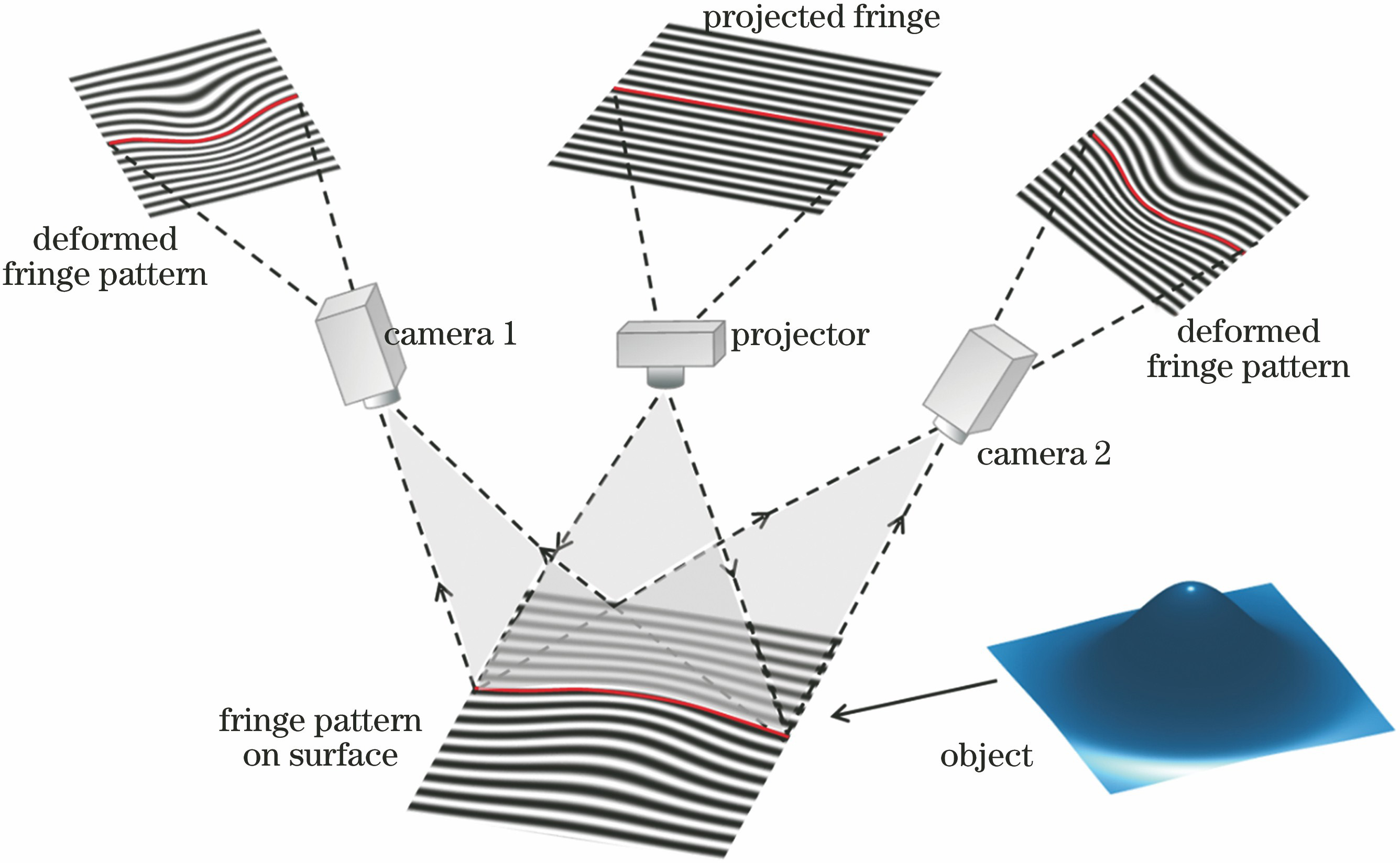
Fig. 1. Illumination model of surface of object
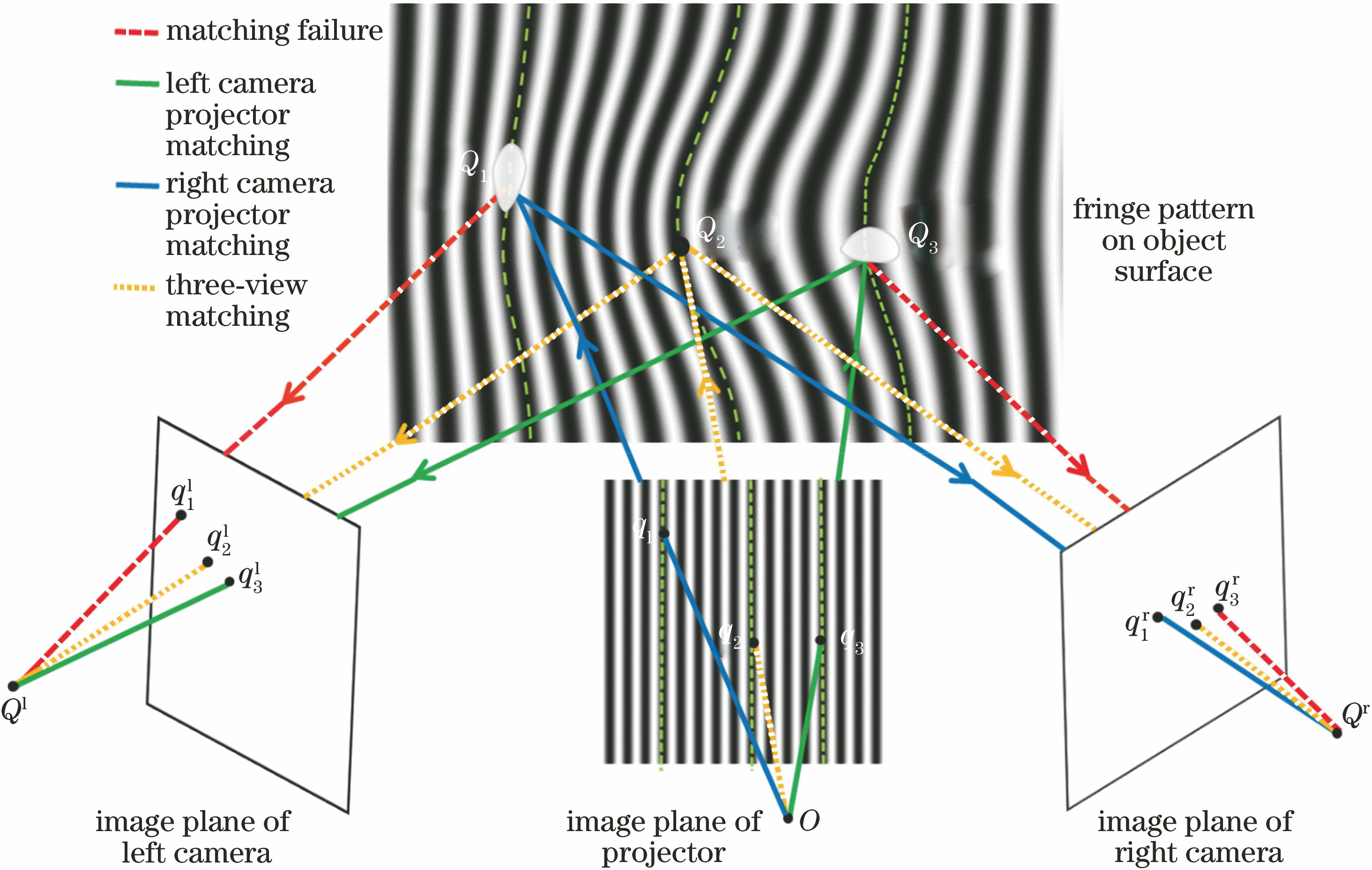
Fig. 2. Measuring principle diagram of fringe projection binocular system
Fig. 3. Geometric diagram of three-view matching
Fig. 4. Experimental setup
Fig. 5. Precision analysis results of proposed method. (a) Measurements of standard sphere; (b) error distribution of standard spherical measurements
Fig. 6. Absolute phase of ceramic cup. (a) Ceramic cup; (b) absolute phase from left camera; (c) absolute phase from right camera; (d) phase change curve in line 560 of Fig. 6 (b); (e) phase change curve in line 600 of Fig. 6 (c)
Fig. 7. 3D reconstruction results of ceramic cup. (a) Reconstruction result of binocular method; (b) reconstruction result of proposed method; (c) ceramic cup 3D data height data of one row
Fig. 8. Measurement images of metallic copper component. (a) Fringe images taken with right camera; (b) absolute phase of right camera; (c) right camera phase mask; (d) fringe images taken by left camera; (e) absolute phase of left camera; (f) left camera phase mask
Fig. 9. Reconstruction result of metallic copper part. (a) Reconstruction result of binocular method; (b) reconstruction result of proposed method
Fig. 10. Reconstruction result of porcelain bottle. (a) Texture image taken by left camera; (b) texture image taken by right camera; (c) reconstruction result of binocular reconstruction (d) reconstruction result of proposed method
|
Table 1. Reconstruction results of standard ball with diameter of 50.7970 mm under different methods unit: mm

Set citation alerts for the article
Please enter your email address
© Copyright 2018-2021 | Chinese Laser Press. All Rights Reserved 沪ICP备15018463号-20