
[in Chinese], [in Chinese], "Bragg accelerator optimization," High Power Laser Sci. Eng. 2, 03000e24 (2014)
- High Power Laser Science and Engineering
- Vol. 2, Issue 3, 03000e24 (2014)
Abstract
Keywords
1. Introduction
X-ray sources based on Compton scattering of a laser from a relativistic counter-propagating electron beam (e-beam) have recently drawn increasing interest due to several potential advantages over magnetostatic free electron lasers (FELs), such as compact size, low-cost operation, and reduced e-beam energy requirements. Recent work[
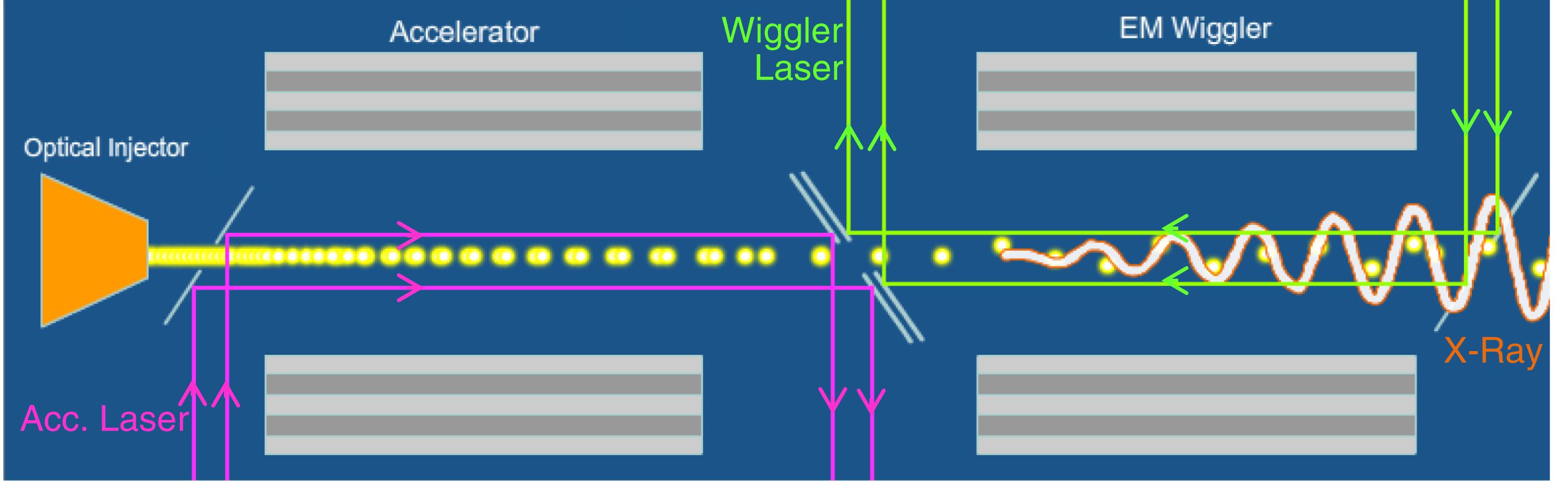
Based on this configuration, we proposed a Bragg configuration based X-FEL operating in the collective regime. The full system consists of three main components (Figure  mode. The co-propagating laser which accelerates the electrons is dumped at the end. Next, the electrons are transported into a second Bragg waveguide. This structure supports a TEM laser mode in the vacuum core (TM mode at the Bragg layers) counter-propagating to the e-beam – the latter acts as an
In this study we focus on the Bragg accelerator. Structure-based laser-driven linear accelerators have been the subject of intense investigation, primarily for use with relativistic particles, where obtaining high energies in compact geometries is desired.
To accelerate particles efficiently, EM waves must be guided or confined to the region in which the particles travel. An electric field component in the direction of desired acceleration is strictly necessary. Traditionally, EM waves have been confined to a vacuum channel surrounded by metallic structures. Field confinement can also be achieved through surrounding dielectric layers where reflections from different layers interfere constructively (Bragg reflection).
A planar Bragg waveguide[ , surrounding alternating periodic layers (
 ,
,  ).
).
The layers are made of two lossless dielectric materials; the first layer has a relative dielectric coefficient  . For single-mode operation:
  . For an optical accelerator having a
  , thus creating the need for a Bragg structure with a matching layer[
The present study is organized as follows: A self-consistent solution for maximum gradient is presented in Section
2. Accelerating gradient
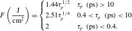
For assessment of the accelerating gradient, we examine the maximum energy flux that can be sustained by the structure; typically, this occurs at the vacuum–dielectric interface, where  . The material is characterized by the fluence (
 ), which represents the energy per unit surface before breakdown occurs. Consequently, the threshold for a pulse of duration
  is determined by
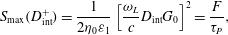 (1)
(1) is the accelerating field gradient,
  is the laser frequency and
  is the vacuum impedance. We rely on the three EM field components of the accelerating mode in the vacuum region
 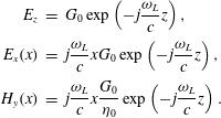 (2)
(2) (3)
(3)In RF-based accelerators, the radiation wavelength is typically more than 10 cm in length, thus we may use  electrons in a
  bunch. Assuming similar dimensions in the transverse directions, we realize that the density of electrons is on the order of
  . If the density is kept the same in the optical regime, say
  , the micro-bunch needs to be on the order of 30 nm long, 100 nm high and, assuming a sheet-beam about
  wide, then the number of electrons in one optical micro-bunch is 300. In spite of this clearly being a very rough estimate, in order to accelerate a significant number of electrons, and keep the electron density as in an RF machine, we need to use a multiple number of periods of the accelerating mode, thus the accelerated bunch is actually a
Moreover, it is strictly necessary to use a pre-bunched beam at optical wavelengths before injection into the optical accelerator. Without the pre-bunching, the beam energy spread is too large to be useful. Energy modulation converted into a density modulation may also lead to increased efficiency in the accelerator. A configuration of modulator and chicane may be used as a pre-buncher injector to increase the number of electrons in the optimal phase of the accelerating laser. An efficient method for bunching the beam at optical wavelengths was suggested in[
An assessment of the laser pulse duration requires one to take into consideration that the EM wave propagates at the group/energy velocity whereas the electrons propagate virtually at the speed of light in vacuum. For full overlap of the two pulses, the duration of the EM pulse is
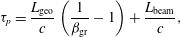 (4)
(4) is the train length,
  represents the number of micro-bunches in the train, and
  is the laser wavelength in vacuum. The geometrical length of the structure is
  , where
  is the relativistic factor and is set by the resonance condition in an EM wiggler. As an example, for a laser wavelength of 1 micron and a radiation wavelength of X-rays
  we get
  .
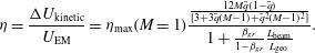
.Due to the constraint imposed by the fluence and for the specified energy ( ), the maximum accelerating gradient depends on two parameters: the clearance of the structure (
 ) and the number of micro-bunches in the train (
 ). Note the interdependence between the various parameters requires a self-consistent solution: the laser field depends on the laser pulse duration, which in turn depends on the train’s total charge and the gradient itself.
| ( | (kW) | (ps) | (ps) | ( | (m) | ||
|---|---|---|---|---|---|---|---|
 | 0.7 | 35.56 |  | 171 | 18.83 | 0.424 | 0.038 |
 | 0.66 | 117.77 | 35 | 216 | 21.2 | 0.424 | 0.04 |
Table 1. Typical Values of the Parameters for  .
.
A self-consistent solution is illustrated in Figure  micro-bunches, the gradient is virtually independent of
  (see Figure
  the gradient decreases for the same clearance. Figure
  . Further simulations show it is better to use a lower dielectric coefficient for the first layer, and in order to achieve a gradient of
  we need to replace the silica with a material whose typical fluence is higher by a factor of 1.5 – assuming the pulse dependence is the same. Typical values of the parameters for
  are given in Table
At this point it warrants making a comment regarding a more realistic scenario: The wake generated by the accelerated bunches tends to reduce the laser field – this is the well known beam-loading effect. Consequently, in the presence of the electrons, the field experienced by the structure is thus reduced accordingly for a given fluence, the applied gradient may be significantly higher. In the context of the fluence effect we consider the worst case scenario and ignore this process. Taking it into consideration, we estimate that the accelerating gradient will be enhanced.
3. Optimal charge
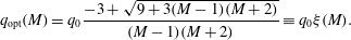
Given the accelerating gradient  , which is evaluated self-consistently, we now calculate the optimal number of electrons in a micro-bunch injected into the acceleration module. Optimum charge occurs for maximum efficiency of the acceleration process. We can interpret the reason for this optimum as follows: for a given accelerating gradient, if the accelerated charge is small, the energy transferred is negligibly small (zero). At the other extreme, when the charge is large, beam loading may suppress the effective accelerating gradient to zero; therefore, again, the transferred energy is minuscule. Between these two ‘zeros’ the function of energy transferred is expected to have a maximum.
3.1. Single bunch
In the single bunch case ( , the efficiency of the acceleration process may be determined as
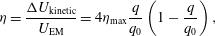 (5)
(5) is the charge for which the wake generated by the bunch balances the laser gradient – in other words, there is no net acceleration. The maximum value of efficiency, occurring for
  , is determined by the projection of the total deceleration, represented by
  , on the fundamental mode, represented in turn by
  – explicitly,
  ;
;  is the weight function of the first mode[
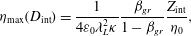 (6)
(6) ,
,  , and
, and  are dependent on the vacuum clearance[
 along which a charged-line propagates, the wake coefficient associated with the decelerating field is
 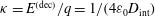 (see Section
 The maximum efficiency itself has an optimum at  (Figure
3.2. Train of micro-bunches
For the case of train of  micro-bunches, the beam-loading causes different micro-bunches to experience different effective accelerating gradients. In order to eliminate this effect, the laser pulse must be tapered according to
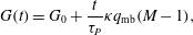 (7)
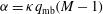
(7) is the charge in one micro-bunch; tacitly assuming that all micro-bunches are identical. It is assumed that for a sufficiently large number of
  the weight function of the first mode is dominant, i.e.,
  .
.  is the wake coefficient, which depends on the structure and number of accelerated micro-bunches. The wake coefficients for a single bunch and train of micro-bunches are different; however, since the laser is tapered, we consider the wake coefficient for a single bunch and a single discontinuity.
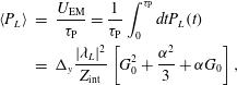
The EM energy injected into the system may be readily calculated using
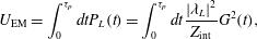 (8)
(8) (9)
(9) (10)
(10) ) we get
  , and get the maximum efficiency which was calculated explicitly for a single bunch. (iii) Comparing to the latter case, the efficiency more than doubled for
  . (iv) Figure
 Another perspective of the energy conversion efficiency is the total amount of charge accelerated and its distribution among the various numbers of micro-bunches. The number of electrons in a train as a function of the number of micro-bunches is almost constant  . Thus, for larger values of
  , the number of electrons in a micro-bunch drops. Figure
  and
and  on the vacuum clearance.
The average power per unit length ( ) of the tapered laser is given by
 (11)
(11) . It has a maximum for
  (Figure
  , whereas
  decreases. As an example, for
  and
and  micro-bunches in the train, the average tapered laser power is 117 kW, whereas for
  the latter is only 11 kW. It should be pointed out that pulse shaping can be done using several methods, such as spatial light modulators, adaptive beam shaping and fixed masks[
4. Wake coefficient – single bunch
In this section we determine and investigate the wake coefficient ( ) for a single bunch (in the following section we repeat this for a train of micro-bunches). Both are essential for establishing the optimal charge in the micro-bunch and determining the beam loading effect.
A laser pulse accelerates a point charge  moving in a vacuum tunnel of planar Bragg acceleration structure and generates an EM wake (Cerenkov radiation). Associated with this wake there is a decelerating electric field which, by virtue of the linearity of Maxwell’s equations, is proportional to the charge, namely
  , where the wake coefficient
  depends on the structure.
The vacuum–dielectric discontinuity generates a reflected wave that can affect the point charge. Any reflection occurring further away from the first discontinuity reaches the structure’s axis only after the point charge has passed–thus it may affect only trailing micro-bunches.
In the absence of reflections, the wake coefficient is determined by the structure (Appendix
 (12)
(12)In the presence of reflections, for a single bunch, only the first discontinuity affects a line-charge. However, we demonstrate that quantitatively using a previously defined formulation[ is
is
 (13)
(13) is the reflection coefficient of the structure – including the effect of the first (matching) layer as well as the ‘Bragg layers’. Numerical evaluation of Equation (
 , with an error of less than 0.1% – i.e., the wake coefficient for a single bunch including reflections is almost equal to the wake coefficient with no reflections. In fact, it is possible to demonstrate analytically that since reflection reaches the axis behind the charged-line micro-bunch,
  .
.5. Wake coefficient – train of bunches
In the case of a train of micro-bunches the field spatial distribution trailing the particle is strongly affected. The Bragg dielectric structure allows energy to escape from the structure through the layers, and the trailing bunches are less affected by the wake field – except eigenmodes of the structure.
For a train of  micro-bunches, of length
  each, separated by one wavelength
  (Figure
 (14)
(14) is the relative length of the micro-bunch and
  are the weights[
Several observations are evident:  decays as
  and the ‘sinc’ function acts as a low-pass filter (Figure
  has an effect on the non-fundamental modes, i.e.,
  .
.  is independent of the number of micro-bunches (
 ) and thus remains the same. The projection of the wake on the fundamental mode (
 -weight of the first mode) increases with the number of micro-bunches in the train (since higher frequencies are suppressed). Therefore, we should be able to enhance to some extent the efficiency for
  , and increase the amount of charge accelerated.
Our simplified model allows all  harmonics, since the dielectric coefficient is independent of frequency. In practice, the dielectric function is frequency dependent and, as a result, the higher harmonics are also suppressed.
6. Conclusions
The maximum accelerating gradient is evaluated self-consistently based on the constraints imposed by the pulse duration and fluence. It depends on two parameters: the clearance of the structure ( ) and the number of micro-bunches in the train (
 ). In the worst case scenario, it may reach levels of
  .
.
Optimum charge occurs for maximum efficiency of the acceleration process. For a train of micro-bunches, two constraints must be satisfied: the laser pulse duration must be longer than the macro bunch length and the laser’s envelope must be tapered to compensate for the beam loading, ensuring uniform gradient acceleration of all micro-bunches. The maximum efficiency has an optimal value ( ) which depends on two parameters: a weak dependence on the vacuum clearance and a strong dependence on the number of micro-bunches.
The optimal number of electrons to be accelerated is determined by the laser field and the maximum efficiency requirement. For  , the number electrons in a micro-bunch is
  , while the total number of electrons in the train is almost constant (
 ). There is weak dependence of
  and
and  on the vacuum clearance.
The optimal charge in the micro-bunch and the beam loading effect are also determined by the wake coefficient. The latter is a property of the structure and refers to the decelerating field. The maximum efficiency increases with the number of micro-bunches in the train since higher frequencies are suppressed.
References
[1] V. Karagodsky, D. Schieber, L. Schächter. Phys. Rev. Lett., 104, 024801(2010).
[2] A. Mizrahi, L. Schächter. Phys. Rev. E, 70, 016505(2004).
[3] A. Mizrahi, L. Schächter. Opt. Express, 12, 3156(2004).
[5] E. Hemsing, D. Xiang. Phys. Rev. Spec. Top. Accel. Beams, 16, 010706(2013).
[7] L. Schächter, R. L. Byer, R. H. Siemann. AAC, 23(2002).
[8] K. Bane, G. Stupakov. Phys. Rev. Spec. Top. Accel. Beams, 6, 024401(2003).


Set citation alerts for the article
Please enter your email address

© Copyright 2018-2021 | Chinese Laser Press. All Rights Reserved 沪ICP备15018463号-20