• Photonics Research
  • Vol. 9, Issue 4, 507 (2021)
Minkyu Kim1, Min-Hyeong Kim1、2, Youngkwan Jo1, Hyun-Kyu Kim1, Stefan Lischke3, Christian Mai3, Lars Zimmermann3、4, and Woo-Young Choi1、*
Author Affiliations
  • 1Department of Electrical and Electronic Engineering, Yonsei University, 03722 Seoul, Republic of Korea
  • 2Current address: Samsung Electronics, Hwasung, 18448 Gyeonggi-do, Republic of Korea
  • 3IHP, Im Technologiepark 25, 15236 Frankfurt (Oder), Germany
  • 4Technische Universität Berlin, Einsteinufer 25, 10587 Berlin, Germany
  • show less
    DOI: 10.1364/PRJ.413407 Cite this Article Set citation alerts
    Minkyu Kim, Min-Hyeong Kim, Youngkwan Jo, Hyun-Kyu Kim, Stefan Lischke, Christian Mai, Lars Zimmermann, Woo-Young Choi. Silicon electronic–photonic integrated 25 Gb/s ring modulator transmitter with a built-in temperature controller[J]. Photonics Research, 2021, 9(4): 507 Copy Citation Text show less
    Block diagram of the silicon photonic WDM transmitter with ring resonators.
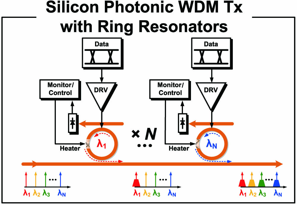
    Fig. 1. Block diagram of the silicon photonic WDM transmitter with ring resonators.
    Measured transmission curves and 25 Gb/s eye diagrams for different temperatures.
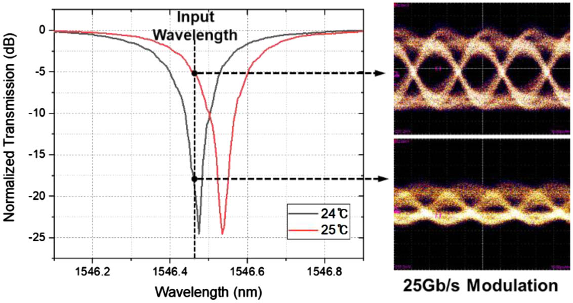
    Fig. 2. Measured transmission curves and 25 Gb/s eye diagrams for different temperatures.
    (a) Block diagram and (b) fabricated chip photo of the monolithic silicon photonic transmitter with a temperature controller.
    Fig. 3. (a) Block diagram and (b) fabricated chip photo of the monolithic silicon photonic transmitter with a temperature controller.
    Schematic of the RM driver circuits.
    Fig. 4. Schematic of the RM driver circuits.
    Schematic of the OMA monitor block.
    Fig. 5. Schematic of the OMA monitor block.
    Schematic of the temperature sensor ADC.
    Fig. 6. Schematic of the temperature sensor ADC.
    Timing diagram for the temperature control operation.
    Fig. 7. Timing diagram for the temperature control operation.
    Simulation results for the temperature control operation with Verilog-A behavior models.
    Fig. 8. Simulation results for the temperature control operation with Verilog-A behavior models.
    (a) Photo and (b) block diagram of the measurement setup.
    Fig. 9. (a) Photo and (b) block diagram of the measurement setup.
    Measured transmission curve of the RM with different on-chip heater powers.
    Fig. 10. Measured transmission curve of the RM with different on-chip heater powers.
    (a) Measured I-V curve for the temperature sensor and (b) measured ADC output code with different temperatures.
    Fig. 11. (a) Measured I-V curve for the temperature sensor and (b) measured ADC output code with different temperatures.
    Measurement results for heater voltage (VHeater) and RM OMA (VOMA) in calibration and lock modes.
    Fig. 12. Measurement results for heater voltage (VHeater) and RM OMA (VOMA) in calibration and lock modes.
    Measurement results in the lock mode with thermal stress showing (a) heater voltage (VHeater) and (b) 25 Gb/s eye diagrams.
    Fig. 13. Measurement results in the lock mode with thermal stress showing (a) heater voltage (VHeater) and (b) 25 Gb/s eye diagrams.
     15 JSCC [12]18 ISSCC [13]20 ISSCC [14]16 JSSC [15]16 JSSC [16]19 JLT [17]This Work
    Process130 nm SOI SiPh + 65 nm CMOS100 nm SOI SiPh + 65 nm CMOSSiPh + 28 nm CMOS130 nm SOI SiPh + 40 nm CMOS45 nm CMOS SOI0.25 μm BiCMOS0.25 μm Photonic BiCMOS
    Wavelength1550 nm1310 nm1310 nm1550 nm1180 nm1550 nm1550 nm
    Data Rate25 Gb/s10 Gb/s112 Gb/s2 Gb/s5 Gb/s25 Gb/s25 Gb/s
    Driver IntegrationYes (Wire-bonded)Yes (3D face-to-face)Yes (3D face-to-face)Yes (Wire-bonded)Yes (Monolithic)NoYes (Monolithic)
    Controller IntegrationNo (Off-chip PD)Yes (3D face-to-face)Yes (3D face-to-face)No (Off-chip DAC)Yes (Monolithic)No (Off-chip PD)Yes (Monolithic)
    SchemeAverage powerAnalog closed-loop w/digital reconfig.Normalized average power stabilizationOMA monitor w/slope-quantizationBit-statisticsOMA monitor with power detector & without step approachOMA monitor with temperature sensing & PID control
    Manual Reference SettingYesYesYesNoNoNoNo
    Resonance Wavelength Tuning RangeN/AN/ANot reported (50 mW power dissipation)5 nm2.5 nm0.55 nm3.27 nm
    Temp. Controller Powera0.17 mW0.15 mWNot reported2.9 mW0.72 mW3.91 mW3.325 mW
    Table 1. Performance Comparison for Silicon Photonic Transmitters with Ring Modulators and Temperature Controllers
    Minkyu Kim, Min-Hyeong Kim, Youngkwan Jo, Hyun-Kyu Kim, Stefan Lischke, Christian Mai, Lars Zimmermann, Woo-Young Choi. Silicon electronic–photonic integrated 25 Gb/s ring modulator transmitter with a built-in temperature controller[J]. Photonics Research, 2021, 9(4): 507
    Download Citation