• Advanced Photonics Nexus
  • Vol. 3, Issue 3, 036003 (2024)
Bowang Shu1, Yuqiu Zhang1、*, Hongxiang Chang1, Shiqing Tang1, Jinyong Leng1、2、3, and Pu Zhou1、*
Author Affiliations
  • 1National University of Defense Technology, College of Advanced Interdisciplinary Studies, Changsha, China
  • 2National University of Defense Technology, Nanhu Laser Laboratory, Changsha, China
  • 3National University of Defense Technology, Hunan Provincial Key Laboratory of High Energy Laser Technology, Changsha, China
  • show less
    DOI: 10.1117/1.APN.3.3.036003 Cite this Article Set citation alerts
    Bowang Shu, Yuqiu Zhang, Hongxiang Chang, Shiqing Tang, Jinyong Leng, Pu Zhou. Integrated coherent beam combining system for orbital-angular-momentum shift-keying-based free-space optical links[J]. Advanced Photonics Nexus, 2024, 3(3): 036003 Copy Citation Text show less
    Principles of structured optical communication by CBA. (a) The first part: distributed tiled apertures in the near field for generation of multiplexed optical vortices. (b) The second part: filtering and propagation process of the multiplexed OAM modes. (c) The last part: demultiplexing of OAM modes by the designed diffraction grating.
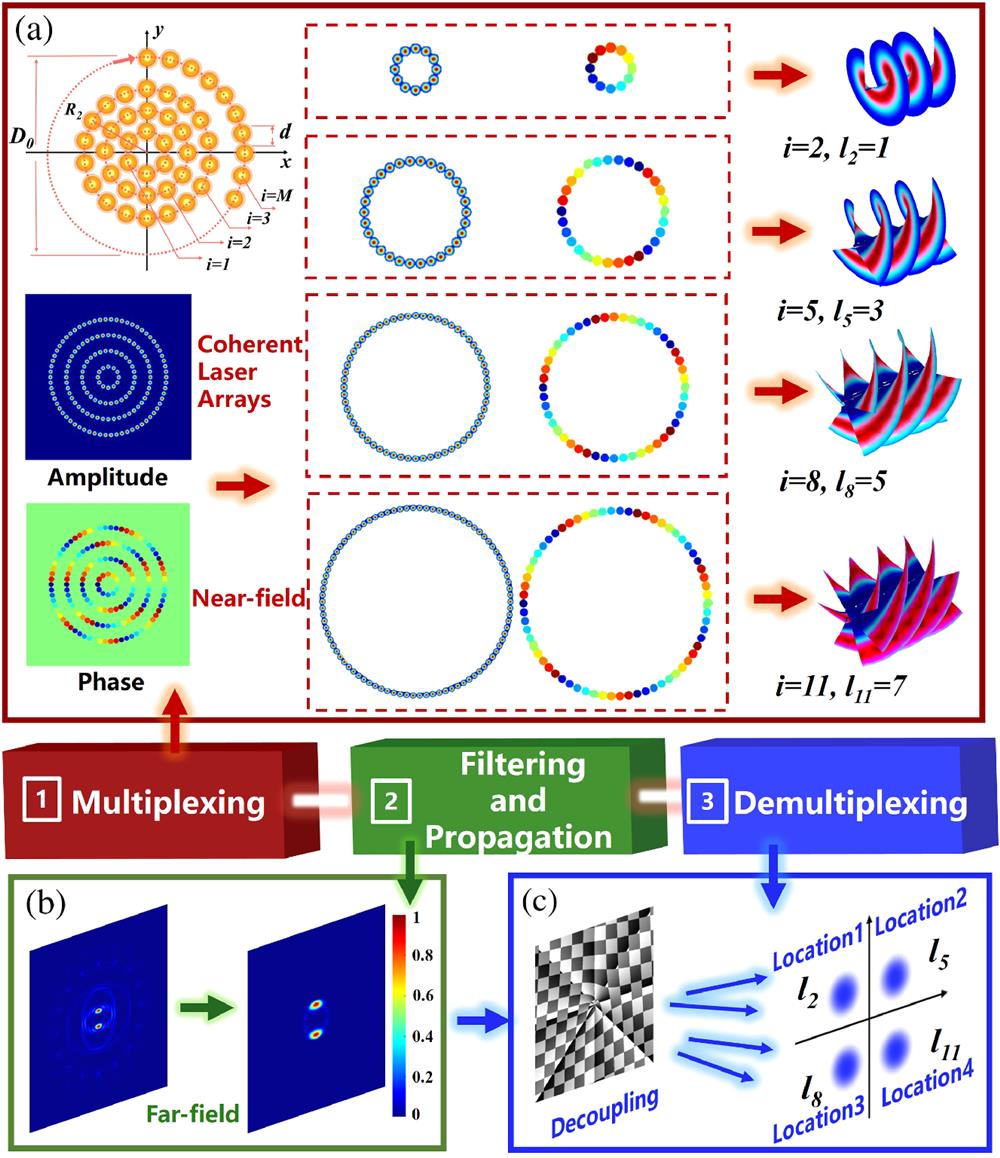
    Fig. 1. Principles of structured optical communication by CBA. (a) The first part: distributed tiled apertures in the near field for generation of multiplexed optical vortices. (b) The second part: filtering and propagation process of the multiplexed OAM modes. (c) The last part: demultiplexing of OAM modes by the designed diffraction grating.
    Graphical diagram of CBA for the FSOC system. The detailed components of the experimental setup are CO, collimator; BE, beam expander; HWP, half-wave plate; P1–P2, polarizers; L1–L3, lenses; CCD, charge-coupled device; A-SLM, amplitude type spatial light modulator; P-SLM1 and P-SLM2, phase-type spatial light modulators.
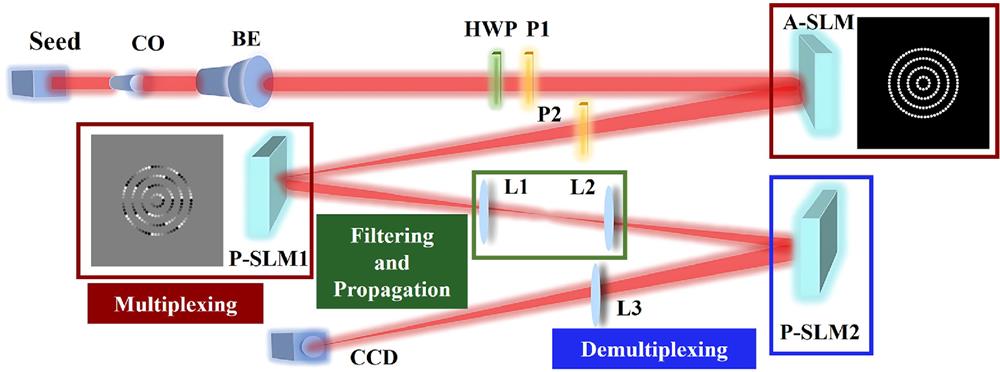
    Fig. 2. Graphical diagram of CBA for the FSOC system. The detailed components of the experimental setup are CO, collimator; BE, beam expander; HWP, half-wave plate; P1–P2, polarizers; L1–L3, lenses; CCD, charge-coupled device; A-SLM, amplitude type spatial light modulator; P-SLM1 and P-SLM2, phase-type spatial light modulators.
    Verification results of OAM mode multiplexing by CBA. (a1)–(a15) Simulated results of OAM mode multiplexing in the far field. (b1)–(b15) Experimental results of OAM mode multiplexing in the far field.
    Fig. 3. Verification results of OAM mode multiplexing by CBA. (a1)–(a15) Simulated results of OAM mode multiplexing in the far field. (b1)–(b15) Experimental results of OAM mode multiplexing in the far field.
    Intensity and phase distributions of OAM mode multiplexing by two sub-arrays with phase differences or with different sub-apertures. (a1)–(a3) Near-field phase distribution of two sub-arrays with phase differences. (b1)–(b3) Simulated results of multiplexed OAM modes by two sub-arrays with phase differences. (c1)–(c3) Corresponding experimental results. (d1)–(d3) Near-field phase distribution of two sub-arrays with different sub-apertures. (e1)–(e3) Simulated results of multiplexed OAM modes by two sub-arrays with different sub-apertures. (f1)–(f3) Corresponding experimental results.
    Fig. 4. Intensity and phase distributions of OAM mode multiplexing by two sub-arrays with phase differences or with different sub-apertures. (a1)–(a3) Near-field phase distribution of two sub-arrays with phase differences. (b1)–(b3) Simulated results of multiplexed OAM modes by two sub-arrays with phase differences. (c1)–(c3) Corresponding experimental results. (d1)–(d3) Near-field phase distribution of two sub-arrays with different sub-apertures. (e1)–(e3) Simulated results of multiplexed OAM modes by two sub-arrays with different sub-apertures. (f1)–(f3) Corresponding experimental results.
    Intensity distribution in the far field by spatial filtering between multiplexing and demultiplexing procedures. (a1)–(a15) Simulated results. (b1)–(b15) Corresponding experimental results.
    Fig. 5. Intensity distribution in the far field by spatial filtering between multiplexing and demultiplexing procedures. (a1)–(a15) Simulated results. (b1)–(b15) Corresponding experimental results.
    Verification results of OAM mode demultiplexing by complex forking gratings. (a1)–(a15) Simulated results of OAM mode multiplexing in the far field. (b1)–(b15) Experimental results of OAM mode multiplexing in the far field.
    Fig. 6. Verification results of OAM mode demultiplexing by complex forking gratings. (a1)–(a15) Simulated results of OAM mode multiplexing in the far field. (b1)–(b15) Experimental results of OAM mode multiplexing in the far field.
    Comparison between the simulated intensity proportion of ideal OAM modes and practical OAM modes before and after the demultiplexing process. Results of the codes to be (a1)–(a5) 0001; (b1)–(b5) 1010; (c1) – (c5) 1110, and (d1)–(d5) 1111 as introduced phase errors to be 0, 0.3, 0.6, 1.0, and 1.5, respectively.
    Fig. 7. Comparison between the simulated intensity proportion of ideal OAM modes and practical OAM modes before and after the demultiplexing process. Results of the codes to be (a1)–(a5) 0001; (b1)–(b5) 1010; (c1) – (c5) 1110, and (d1)–(d5) 1111 as introduced phase errors to be 0, 0.3, 0.6, 1.0, and 1.5, respectively.
    Detailed process of data transmission by integrated CBC system. (a) Original input image. (b1)–(b2) Intensity and (c1)–(c2) phase distributions. (d1)–(d2) Far-field patterns and (e1)–(e2) patterns after spatial filtering. (f1)–(f2) OAM mode demultiplexing results. (g1)–(g2) Transferred gray-scale patterns. (h1)–(h2) The encoding results for 0100 and 1010 code elements, respectively. (i) Recovered output image. (j) Error rate at different locations. (k1)–(k4) The separate four Gaussian spots inconsistent with Fig. 8(f2). (k5) Error rate at different thresholds.
    Fig. 8. Detailed process of data transmission by integrated CBC system. (a) Original input image. (b1)–(b2) Intensity and (c1)–(c2) phase distributions. (d1)–(d2) Far-field patterns and (e1)–(e2) patterns after spatial filtering. (f1)–(f2) OAM mode demultiplexing results. (g1)–(g2) Transferred gray-scale patterns. (h1)–(h2) The encoding results for 0100 and 1010 code elements, respectively. (i) Recovered output image. (j) Error rate at different locations. (k1)–(k4) The separate four Gaussian spots inconsistent with Fig. 8(f2). (k5) Error rate at different thresholds.
    Bowang Shu, Yuqiu Zhang, Hongxiang Chang, Shiqing Tang, Jinyong Leng, Pu Zhou. Integrated coherent beam combining system for orbital-angular-momentum shift-keying-based free-space optical links[J]. Advanced Photonics Nexus, 2024, 3(3): 036003
    Download Citation