• Chinese Optics Letters
  • Vol. 16, Issue 3, 030602 (2018)
Fanlong Dong1, Xinhai Zhang1、*, and Feng Song2
Author Affiliations
  • 1Department of Electronics and Electrical Engineering, Southern University of Science and Technology, Shenzhen 518055, China
  • 2Key Laboratory of Weak Light Nonlinear Photonics, Ministry of Education, Nankai University, Tianjin 300457, China
  • show less
    DOI: 10.3788/COL201816.030602 Cite this Article Set citation alerts
    Fanlong Dong, Xinhai Zhang, Feng Song. Thermal expanded core technique applied to high power fiber mode field adapter[J]. Chinese Optics Letters, 2018, 16(3): 030602 Copy Citation Text show less
    Schematic illustration of a thermally expanded core fiber.
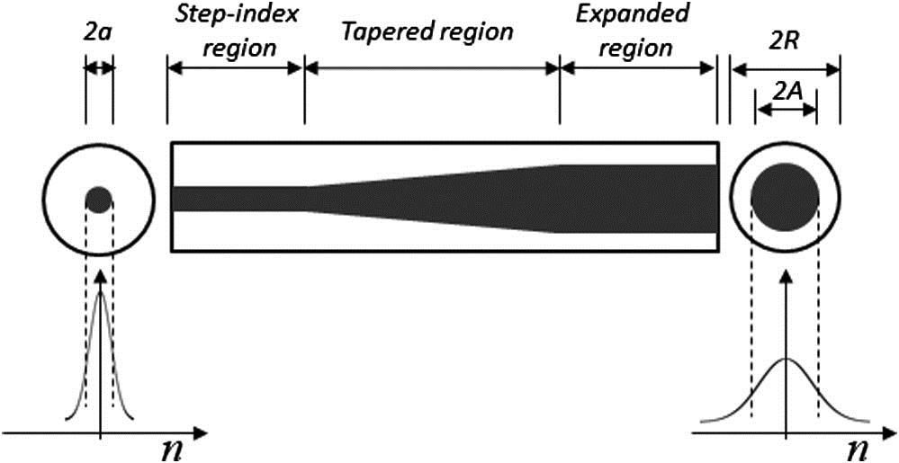
    Fig. 1. Schematic illustration of a thermally expanded core fiber.
    Refractive index profile by the thermal diffusion of the dopant. Initial LMAF’s parameters are a = 7.5 μm, ncl= 1.4495, and Δn =0.0022.
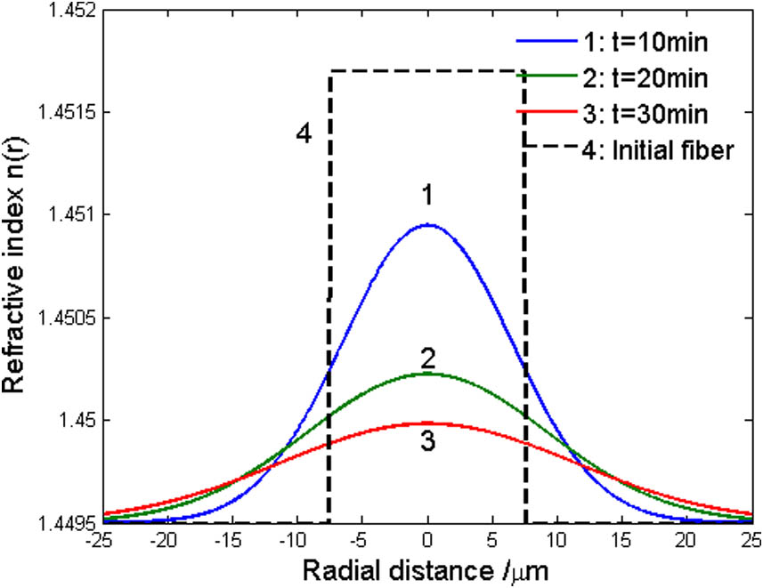
    Fig. 2. Refractive index profile by the thermal diffusion of the dopant. Initial LMAF’s parameters are a = 7.5 μm, ncl=1.4495, and Δn=0.0022.
    Enlargement of the LP01 MFDs at λ = 1.06 μm by the thermal diffusion of the dopant for SMFs and LMAFs.
    Fig. 3. Enlargement of the LP01 MFDs at λ = 1.06 μm by the thermal diffusion of the dopant for SMFs and LMAFs.
    MFDs after the TEC treatment versus the NAs of the initial fibers.
    Fig. 4. MFDs after the TEC treatment versus the NAs of the initial fibers.
    MFD after the TEC treatment versus the core diameter of the initial fibers.
    Fig. 5. MFD after the TEC treatment versus the core diameter of the initial fibers.
    Distribution of LP01 mode field in the MFA.
    Fig. 6. Distribution of LP01 mode field in the MFA.
    Transmission efficiency of the MFA versus the length of the heating region.
    Fig. 7. Transmission efficiency of the MFA versus the length of the heating region.
    Micrographs of the TEC fiber cross-section. (a) Initial SMF 6/125; (b) TEC SMF 6/125; (c) initial LMAF 15/130; (d) TEC LMAF 15/130.
    Fig. 8. Micrographs of the TEC fiber cross-section. (a) Initial SMF 6/125; (b) TEC SMF 6/125; (c) initial LMAF 15/130; (d) TEC LMAF 15/130.
    Schematic illustration measuring the performance of the MFA.
    Fig. 9. Schematic illustration measuring the performance of the MFA.
    Transmission loss of the MFA with TEC treatment.
    Fig. 10. Transmission loss of the MFA with TEC treatment.
    Fanlong Dong, Xinhai Zhang, Feng Song. Thermal expanded core technique applied to high power fiber mode field adapter[J]. Chinese Optics Letters, 2018, 16(3): 030602
    Download Citation