Fanlong Dong, Xinhai Zhang, Feng Song, "Thermal expanded core technique applied to high power fiber mode field adapter," Chin. Opt. Lett. 16, 030602 (2018)
Copy Citation Text
A mode field adapter (MFA) fabricated by the thermal expanded core (TEC) technique is investigated. Firstly, the mode field characteristics of the TEC large mode area fiber (LMAF) are analyzed. Compared with the single-mode fiber (SMF), the mode field diameter of the LMAF enlarged slower than that of the SMF. Secondly, the mode field characteristics of the different fibers with TEC treatment are discussed. Thirdly, the transmission efficiency of the MFA fabricated by the SMF and LMAF is also investigated. Finally, we used the 6/125 μm SMF and 15/130 μm LMAF to fabricate an MFA with transmission efficiency of 92% and the handling power as high as 100 W.
As is known, the dopant in the core of fiber will diffuse to the cladding when the heating temperature exceeds 1300°C. This phenomenon is called the thermal expanded core (TEC). The TEC technique can reduce the index difference between the fiber core and cladding and increase the core diameter and mode field area. Usually, the TEC technique as an effective way to increase the fiber mode field diameter (MFD) has been widely used in the fields of optical fiber information and communications[1–4]. In 1988, Mclandrich[5] first proposed the TEC method; then, a lot of relevant work has been done to study it theoretically and experimentally[6–12]. In 2005, Wang et al. applied the TEC technique of the single mode fiber (SMF) in optical devices, such as fiber connector, isolator, and optical fiber filter[13]. In 2013, Zhou et al. studied the TEC technique for SMF, discussing the relationship between transmission loss and germanium-doped concentration[14]. Li et al. used the 10/130 μm large mode area (LMA) double clad fiber and the 6/125 μm SMF to fabricate a fiber mode field adapter (MFA) by the TEC method[15]. In addition, the TEC technique is also widely used to fabricate the monolithic pump–signal fiber combiner[16,17].
However, most of the current researches about the TEC technique are aimed at SMF, and the related research on the LMA and low numerical aperture (NA) fiber has not been reported. With the rapid development of the LMA all-fiber laser, the TEC technique in this field becomes more and more important. In particular, it is more valuable in reducing fiber connection loss and enhancing the damage threshold of the fiber end face.
In this Letter, we will investigate the refractive index (RI) profile and the mode field characteristics of the TEC LMA fiber (LMAF). The difference of the mode field distribution between the thermally expanded core SMF and LMAF will be discussed. We will simulate the propagation characteristics of the MFA which is fabricated by 6/125 μm SMF and 15/130 μm LMAF in order to obtain the fundamental modal field distribution in the expanded core region of the fiber. Finally, a high coupling efficiency and high handling power MFA will be fabricated by the SMF and LMAF.
Sign up for Chinese Optics Letters TOC. Get the latest issue of Chinese Optics Letters delivered right to you!Sign up now
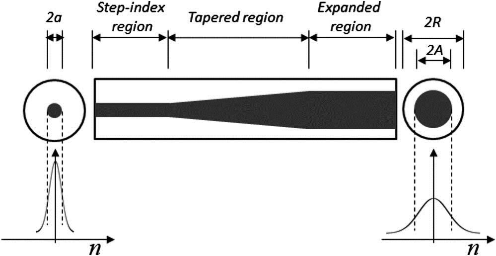
A schematic illustration of a TEC fiber is shown in Fig. 1. The initial fiber with the core radius is , and cladding radius is R before heating. The equivalent core is after thermal expansion. We assume that the heating region of the fiber is very long with respect to the radial size of the fiber, and thus, the heated region of the expanded core is uniform.
Figure 1.Schematic illustration of a thermally expanded core fiber.
According to the characteristics of dopant diffusion in the fiber core, the TEC fiber can be seen as a graded-index fiber. The longitudinal diffusion of the dopant can be ignored, when the heating region is long enough. So that we only discuss the radial diffusion of the dopant, the RI profile of any cross-section of the fiber can be expressed as[7]
Here, is the radial distance, is the RI at any point of the fiber, and are the RI of the core and cladding of the fiber before thermal diffusion, respectively, and is the distribution function of the doped germanium ions.
The diffusion equation in cylindrical coordinates is written as follows: where is the diffusion coefficient of the dopant, and is a function of temperature. It can be expressed by the Arrhenius formula, where is the constant factor of vibration, and is the activation energy of ions; for germanium ions, the value is ; is the thermodynamic temperature, and is the gas constant. Hence, for heating temperatures of 1700°C, the diffusion coefficient of germanium dopants has been determined equal to .
According to the diffusion equation, assume that for the initial dopant concentration in the form of -function, Kliros and Tsironikos[8] obtained where is defined as the equivalent core radius of the fiber after the heat treatment.
According to Eqs. (1) and (4), the RI profile of the TEC fiber is written as
From Eq. (5), we obtained a TEC fiber with a Gaussian-like RI profile.
Figure 2 shows the radial distribution of the RI of the LMAF with the core diameter a=15 μm and NA of 0.08 when the heating time is 10, 20, and 30 min. One can see that the enlargement of the field starts substantially after the RI profile reaches a Gaussian function. With the increasing heating time, the equivalent radius of the fiber core gradually increases. In addition, Eq. (5) shows that the core–cladding RI difference varies inversely with the square of the equivalent radius.
Figure 2.Refractive index profile by the thermal diffusion of the dopant. Initial LMAF’s parameters are a = 7.5 μm, , and .
It is convenient to approximate the fundamental mode () field profile as a Gaussian function for the simulation of the transmission characteristics in the TEC fiber. In our study, the MFD’s enlargement of the mode at = 1.06 μm by the thermal diffusion of the dopants for SMFs and LMAFs is shown in Fig. 3. With the increase of heating time, the MFDs of these fibers enlarged gradually. Compared to the SMF, we find that the MFD of the LMAF increased quicker than that of the SMF. Since the initial MFD of the SMF is smaller, the MFDs could be matched to each other at a special heating time. In Fig. 3, the MFDs of a 6 μm core, 0.14 NA fiber and a 15 μm core, 0.08 NA fiber both reached 18 μm when the heating time is about 6 min. We can use this feature to reduce the splicing loss between the SMF and LMAF in the experiment. In addition, analytical results illustrated in Fig. 3 show that a 6 μm NA 0.14 SMF and a 20 μm NA 0.06 fiber can be matched after a longer heating time.
Figure 3.Enlargement of the MFDs at = 1.06 μm by the thermal diffusion of the dopant for SMFs and LMAFs.
The beam propagating method (BPM) is useful for calculating the wave propagation along a waveguide fiber. Ref. [18] analyzed beam propagation problems in the graded-index SMF in cylindrical coordinates. Amitay et al.[19] calculated the transmission loss of the up-taper fiber using the BPM. Here, the transmission characteristics of a TEC fiber by the BPM is simulated. First, a TEC fiber model with a Gaussian radial and axial RI profile, as shown in Fig. 1, is built. When , the relationship between MFDs after thermal expansion and the NAs of four different initial fibers is analyzed in Fig. 4. It can be seen that the smaller the NA of the initial fibers, the larger the MFDs after the TEC treatment. In most LMAFs, the MFDs are usually smaller than the expanded core diameter. For example, the MFD after the TEC treatment of 20 μm NA 0.06 fiber is about 25 μm when the expanded fiber core is 40 μm. There are exceptions; for the core diameter of 10 μm, NA less than 0.07 initial fiber, it can be seen that the MFD enlarged dramatically after the TEC treatment, which is much larger than the expanded core diameter. This is related to the tiny RI difference between the core and cladding. After thermal diffusion, is much smaller, so that the fiber core will not play a role in confining the beam light in the core. Finally, part of the core is taken as cladding. Naturally, the enlarged MFD is also accompanied by more transmission loss.
Figure 4.MFDs after the TEC treatment versus the NAs of the initial fibers.
In addition, the relationship between the MFDs after the TEC treatment and the core diameters of four different NA initial fibers is also analyzed in Fig. 5. The curves have a saddle shape. First, the MFD decreases along with the decreasing core diameter of the initial fiber. Then, at a certain core diameter, the MFD is the smallest, and any core diameter actually causes an increase in the MFD. For the 6 μm NA 0.09 initial fiber, the MFD is about 17 μm when the core diameter is two times larger than the original.
Figure 5.MFD after the TEC treatment versus the core diameter of the initial fibers.
From Fig. 3, it can be seen that the MFDs of a 6 μm NA 0.14 SMF and a 15 μm NA 0.08 fiber could match each other after the core enlargement treatment. It is feasible that an MFA is designed by these two fibers. In fact, according to the simulation results, the MFA model illustrated in Fig. 6 is fabricated. The mode propagated in the MFA is also presented. The MFD varies substantially with the equivalent core diameter.
The relationship between the transmission efficiency and the length of the heating region is illustrated in Fig. 7. The fitting curve demonstrates that the transmission efficiency increases with the increasing length of the heating region. The highest efficiency seems to be no more than 90%. This means that if even two fibers have the same MFD, the mode field mismatch still exists. Thus, the mode field distribution cannot be completely described by the MFD. In fact, the mode profiles are also related to the mismatch loss, which we will not discuss now.
Figure 7.Transmission efficiency of the MFA versus the length of the heating region.
In the experiment, we use the graphite filament of the Vytran GPX glass processing system to heat the SMF and LMAF. The center temperature of the graphite filament ranges from 500°C to 2000°C, and the length of heating region is about 2–5 mm. First, the 6/125 μm SMF and 15/130 μm LMAF are heated to enlarge their core diameters. A 1064 nm laser source is used to observe the light spot in the core. Figure 8 shows the comparison of MFDs of two kinds of fibers before and after core expansion. As can be seen, there is a significant increase of the MFD for the SMF, and the diameter of the cladding is substantially unchanged after heating. In fact, the changes of the cladding diameter can be ignored during the heating process because we did not stretch the fibers. It is found that the MFD enlarged to 14.5 μm, which is more than two times that of the initial MFD after heating for 5 min. However, there is no significant enlargement for the MFD of the LMAF after the same heating time. Measurement results indicate that the size of the MFD increases from 13 to 16 μm. By continuing to heat the LMAF, the MFD does not change. In addition, it is found that experimental results of the variation of MFDs are consistent with the simulation results.
The SMF and 15/130 LMAF are chosen to fabricate the MFA; the schematic illustration of the measuring device of the MFA is shown in Fig. 9. First, two kinds of fibers are fused together by the Vytran GPX station, and then the transmission efficiency is measured. The results are shown in the subfigure of Fig. 10. Then, we continue heating the splice point to enlarge the fiber core.
Figure 9.Schematic illustration measuring the performance of the MFA.
From Fig. 10, it can be seen that the transmission loss of the MFA drops from 4 dB (see the subfigure) to 0.5 dB after heating the fibers for 5 min. Especially when the launch power is raised to more than 80 W, the loss of MFA is about 0.35 dB. Finally, when the handling power of the MFA goes up to 100 W, the transmission efficiency is about 92%. This result is consistent with the theoretical analysis in Fig. 7. After packaging and cooling, the MFA operates stably for 2 h at 100 W.
Experimental results show that the transmission efficiency of the MFA that adopted TEC technique has been greatly improved. Compared with commercial MFA products, our self-developed MFA has a higher coupling efficiency, higher operating power, better heat treatment capacity, and higher reliability.
We have investigated the characteristics of the TEC fiber and its applications. Also, we analyzed the RI profile and the mode field characteristics of the TEC fibers. By the comparison of the MFD difference between the 6/125 μm SMF and 15/130 μm LMAF, we found that the MFDs could match each other after the TEC treatment process. Unlike the SMF, the MFD of the LMAF is hard to enlarge by the TEC method. In addition, a high coupling efficiency and high handling power MFA with a transmission efficiency of 92% and a handling power as high as 100 W, fabricated by the SMF and LMAF, is presented.
References
[1] Y. W. Zhou, Z. Z. Luo. Acta Photon. Sin., 42, 12(2013).
[2] T. Oda, K. Hirakawa, K. Ichii, S. Yamamoto, K. Aikawa. Optical Fiber Communications Conference and Exhibition(2017).
Fanlong Dong, Xinhai Zhang, Feng Song, "Thermal expanded core technique applied to high power fiber mode field adapter," Chin. Opt. Lett. 16, 030602 (2018)