• Chinese Optics Letters
  • Vol. 14, Issue 3, 030801 (2016)
Jinggao Zheng*, Qun Wei**, Linyao Yu, Mingda Ge, and Tianyi Zhang
Author Affiliations
  • Changchun Institute of Optics, Fine Mechanics and Physics, Chinese Academy of Sciences, Changchun 130033, China
  • show less
    DOI: 10.3788/COL201614.030801 Cite this Article Set citation alerts
    Jinggao Zheng, Qun Wei, Linyao Yu, Mingda Ge, Tianyi Zhang. Simple optical method for small angular displacement measurement based on the astigmatic effect[J]. Chinese Optics Letters, 2016, 14(3): 030801 Copy Citation Text show less
    Schematic diagram of linear displacement measurement based on the astigmatic effect. The shape of the light spot is changed, as the DP varies its axial displacement along the optical axis (z-axis).
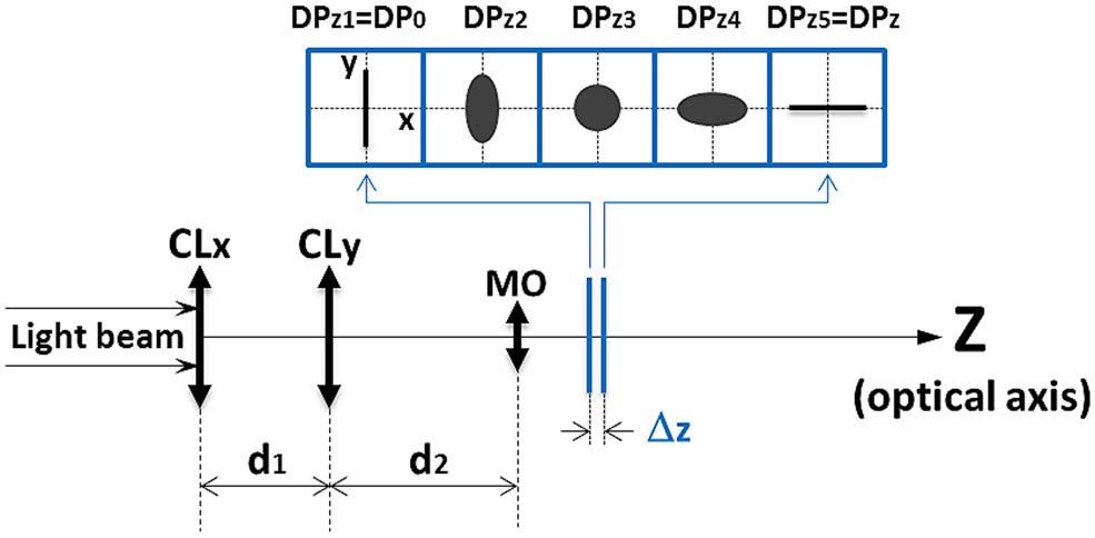
    Fig. 1. Schematic diagram of linear displacement measurement based on the astigmatic effect. The shape of the light spot is changed, as the DP varies its axial displacement along the optical axis (z-axis).
    Schematic diagram of the linear relationship between the axial translation along the optical axis (z-axis) and rotation about an axis (along x-axis) a specified distance L away from the z-axis.
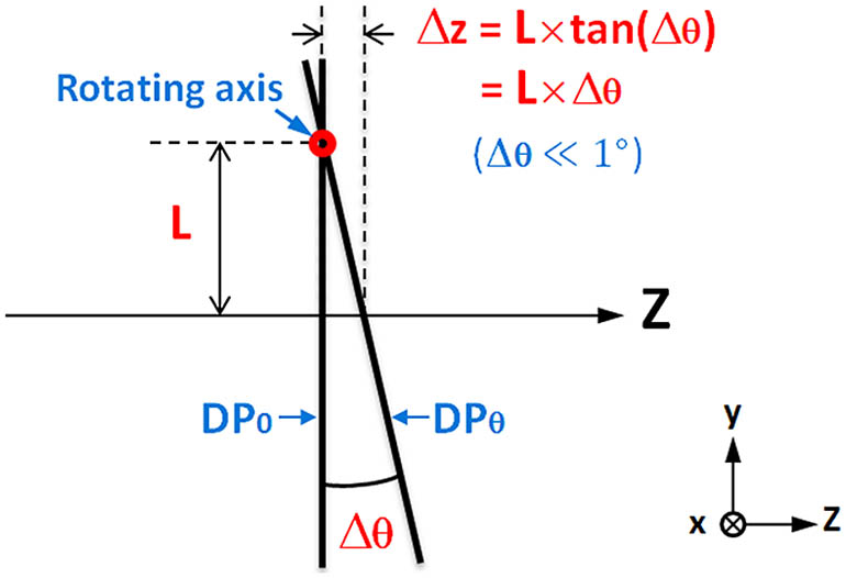
    Fig. 2. Schematic diagram of the linear relationship between the axial translation along the optical axis (z-axis) and rotation about an axis (along x-axis) a specified distance L away from the z-axis.
    Schematic diagram of small-angle measurement based on astigmatic effect. The shape of the light spot is changed, as the DP is rotated about an axis a distance L away from the optical axis (z-axis).
    Fig. 3. Schematic diagram of small-angle measurement based on astigmatic effect. The shape of the light spot is changed, as the DP is rotated about an axis a distance L away from the optical axis (z-axis).
    Schematic diagram of the experimental setup. BE, beam expander.
    Fig. 4. Schematic diagram of the experimental setup. BE, beam expander.
    Laser spot images corresponding to different relative rotated angles of (a) 0°, (b) 0.009°, (c) 0.018°, (d) 0.027°, (e) 0.036°, (f) 0.045°, (g) 0.054°, and (h) 0.063°. SA1 and SA2 in (a) are two symmetrical axes of the laser spot. The numbers 1 to 4 in (h) designate four segmented quadrants.
    Fig. 5. Laser spot images corresponding to different relative rotated angles of (a) 0°, (b) 0.009°, (c) 0.018°, (d) 0.027°, (e) 0.036°, (f) 0.045°, (g) 0.054°, and (h) 0.063°. SA1 and SA2 in (a) are two symmetrical axes of the laser spot. The numbers 1 to 4 in (h) designate four segmented quadrants.
    (a) The quantitative relationship between the FES and rotated angle of the mirror. (b) Δ1: the angle differences between the cubic fit and experimental data that have the same values of FES; Δ2: the angle differences between the linear fit and experimental data that have the same values of FES.
    Fig. 6. (a) The quantitative relationship between the FES and rotated angle of the mirror. (b) Δ1: the angle differences between the cubic fit and experimental data that have the same values of FES; Δ2: the angle differences between the linear fit and experimental data that have the same values of FES.
    Jinggao Zheng, Qun Wei, Linyao Yu, Mingda Ge, Tianyi Zhang. Simple optical method for small angular displacement measurement based on the astigmatic effect[J]. Chinese Optics Letters, 2016, 14(3): 030801
    Download Citation