• Advanced Photonics
  • Vol. 5, Issue 3, 034003 (2023)
Etienne Brasselet*
Author Affiliations
  • University of Bordeaux, CNRS, Laboratoire Ondes et Matière d’Aquitaine, Talence, France
  • show less
    DOI: 10.1117/1.AP.5.3.034003 Cite this Article Set citation alerts
    Etienne Brasselet. Torsion pendulum driven by the angular momentum of light: Beth’s legacy continues[J]. Advanced Photonics, 2023, 5(3): 034003 Copy Citation Text show less
    Selection of a set of pioneering sketches of torsion pendulum arrangements enabling mechanical detection of the transfer of ±Nℏ spin angular momentum per photon, N integer, from fully polarized incident beam. (a) Poynting’s suggestion based on the use of 2N−1 QWPs and LP incident light within a nondissipative process. Prefixes F and S hold for fixed and suspended wave plates, respectively. (b) Beth’s experimental approach providing N=4 using a CP incident beam within a nondissipative process. (c) Carrara’s experimental approach providing N=1 using a CP incident beam within a dissipative process. W, torsion wire; M, mirror; AP, absorbing plate.
    Fig. 1. Selection of a set of pioneering sketches of torsion pendulum arrangements enabling mechanical detection of the transfer of ±N spin angular momentum per photon, N integer, from fully polarized incident beam. (a) Poynting’s suggestion based on the use of 2N1 QWPs and LP incident light within a nondissipative process. Prefixes F and S hold for fixed and suspended wave plates, respectively. (b) Beth’s experimental approach providing N=4 using a CP incident beam within a nondissipative process. (c) Carrara’s experimental approach providing N=1 using a CP incident beam within a dissipative process. W, torsion wire; M, mirror; AP, absorbing plate.
    Illustrative sketches of torsion pendulum experiments dealing with the study of the mechanical effects of angular momentum radiation from a rotating dipole. (a) Apparatus to detect and measure the in-plane orbital angular momentum of the field from dissipative angular momentum transfer to matter in the microwave domain from a cotton wire pendulum.23" target="_self" style="display: inline;">23 (b) Apparatus to detect and measure the torque exerted on the source itself in the radiowave domain from a steel wire pendulum.25" target="_self" style="display: inline;">25 The electromagnetic angular momentum flux flows up or down depending on the direction of rotation of the dipole; see the corresponding mechanical motion indicated by solid/dashed arrow. TA, turnstile antenna; EPS, electric power supply connected to the antenna that is (a) fixed to a rigid post or (b) left free to rotate.
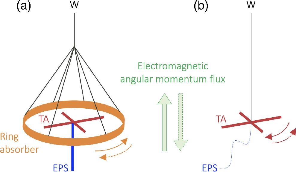
    Fig. 2. Illustrative sketches of torsion pendulum experiments dealing with the study of the mechanical effects of angular momentum radiation from a rotating dipole. (a) Apparatus to detect and measure the in-plane orbital angular momentum of the field from dissipative angular momentum transfer to matter in the microwave domain from a cotton wire pendulum.23 (b) Apparatus to detect and measure the torque exerted on the source itself in the radiowave domain from a steel wire pendulum.25 The electromagnetic angular momentum flux flows up or down depending on the direction of rotation of the dipole; see the corresponding mechanical motion indicated by solid/dashed arrow. TA, turnstile antenna; EPS, electric power supply connected to the antenna that is (a) fixed to a rigid post or (b) left free to rotate.
    Illustration of two kinds of fully integrated optomechanical torsional dynamics experiments driven by a waveguided pump light exciting torsional motion of the waveguide itself. (a) Suspended birefringent silicon waveguide, for nondissipative angular momentum transfer demonstration. Scanning electron microscope image from Ref. 31. (b) Suspended isotropic optical nanofiber (subwavelength diameter) obtained by pulling a standard optical fiber locally molten using a flame brushing technique, for dissipative angular momentum transfer demonstration.32" target="_self" style="display: inline;">32 In both cases, the torsional dynamics is monitored by optical means via (a) nanobeam motion and (b) strain-induced birefringence; see text for details.
    Fig. 3. Illustration of two kinds of fully integrated optomechanical torsional dynamics experiments driven by a waveguided pump light exciting torsional motion of the waveguide itself. (a) Suspended birefringent silicon waveguide, for nondissipative angular momentum transfer demonstration. Scanning electron microscope image from Ref. 31. (b) Suspended isotropic optical nanofiber (subwavelength diameter) obtained by pulling a standard optical fiber locally molten using a flame brushing technique, for dissipative angular momentum transfer demonstration.32 In both cases, the torsional dynamics is monitored by optical means via (a) nanobeam motion and (b) strain-induced birefringence; see text for details.
    Macroscopic torsion pendulum systems for the mechanical demonstration of orbital angular momentum transfer from light to matter. (a) Nondissipative approach consisting of a suspended pair of cylindrical lenses distant by 2f with f the focal length, which was proposed in Ref. 1 and implemented in Ref. 36, yet unsuccessfully. (b) Dissipative approach implemented in Ref. 37. The blue rings refer to the doughnut-shaped transverse intensity profile of a Laguerre–Gaussian beam with azimuthal index ±l, which carries ±lℏ per photon along the beam propagation direction.
    Fig. 4. Macroscopic torsion pendulum systems for the mechanical demonstration of orbital angular momentum transfer from light to matter. (a) Nondissipative approach consisting of a suspended pair of cylindrical lenses distant by 2f with f the focal length, which was proposed in Ref. 1 and implemented in Ref. 36, yet unsuccessfully. (b) Dissipative approach implemented in Ref. 37. The blue rings refer to the doughnut-shaped transverse intensity profile of a Laguerre–Gaussian beam with azimuthal index ±l, which carries ±l per photon along the beam propagation direction.
    Revised illustration of the helical mode cavity design proposed by Battacharya and Meystre41" target="_self" style="display: inline;">41 (in Ref. 41, the displayed handedness of the helical mirrors do not match the required self-consistency for the building up of a cavity mode and here we also provide the correct orbital angular momentum content for the field inside and outside the optical cavity. Similar issues appear in Ref. 42.) that opened up the prediction of various kinds of entanglements involving light and matter and light–matter.42" target="_self" style="display: inline;">42–44" target="_self" style="display: inline;">–44 All helical reflective surfaces have the same handedness and nλ/2 step height (n positive integer). The incident field is a Gaussian beam and the colored arrows refer to contributions of various kinds: purely extracavity (green), purely intracavity (red), extracavity arising from intracavity (blue). In the sketched example, on the one hand, the reflection on the oscillating helical mirror removes nℏ orbital angular momentum per photon along z. On the other hand, the static helical element, which is a partially reflective split-disk mirror with a helical ramp, preserves the orbital state in transmission while its extracavity (intracavity) side removes (adds) nℏ orbital angular momentum per photon along z upon reflection. Using helical mirrors with opposite handedness reverses the sign of the orbital angular momentum changes.
    Fig. 5. Revised illustration of the helical mode cavity design proposed by Battacharya and Meystre41 (in Ref. 41, the displayed handedness of the helical mirrors do not match the required self-consistency for the building up of a cavity mode and here we also provide the correct orbital angular momentum content for the field inside and outside the optical cavity. Similar issues appear in Ref. 42.) that opened up the prediction of various kinds of entanglements involving light and matter and light–matter.4244" target="_self" style="display: inline;">44 All helical reflective surfaces have the same handedness and nλ/2 step height (n positive integer). The incident field is a Gaussian beam and the colored arrows refer to contributions of various kinds: purely extracavity (green), purely intracavity (red), extracavity arising from intracavity (blue). In the sketched example, on the one hand, the reflection on the oscillating helical mirror removes n orbital angular momentum per photon along z. On the other hand, the static helical element, which is a partially reflective split-disk mirror with a helical ramp, preserves the orbital state in transmission while its extracavity (intracavity) side removes (adds) n orbital angular momentum per photon along z upon reflection. Using helical mirrors with opposite handedness reverses the sign of the orbital angular momentum changes.
    Sketches of torsion pendulum arrangements enabling mechanical detection of the transfer of orbital angular momentum from sound to matter by (a) dissipative and (b) nondissipative means. The inset of panel (b) shows the designed (bottom) and fabricated (top) 3D printed helically corrugated plates acting as a reflective acoustic vortex generator used for experimental demonstration.58" target="_self" style="display: inline;">58
    Fig. 6. Sketches of torsion pendulum arrangements enabling mechanical detection of the transfer of orbital angular momentum from sound to matter by (a) dissipative and (b) nondissipative means. The inset of panel (b) shows the designed (bottom) and fabricated (top) 3D printed helically corrugated plates acting as a reflective acoustic vortex generator used for experimental demonstration.58
    Etienne Brasselet. Torsion pendulum driven by the angular momentum of light: Beth’s legacy continues[J]. Advanced Photonics, 2023, 5(3): 034003
    Download Citation