Author Affiliations
1Guangxi Key Laboratory of Spatial Information and Geomatics, Guilin University of Technology, Guilin 541006, China2School of Microelectronics, Tianjin University, Tianjin 300072, China3College of Mechanical and Control Engineering, Guilin University of Technology, Guilin 541006, China4College of Earth Sciences, Guilin University of Technology, Guilin 541006, China534 Research Institute of China Electronics Technology Group Corporation, Guilin 541004, Chinashow less
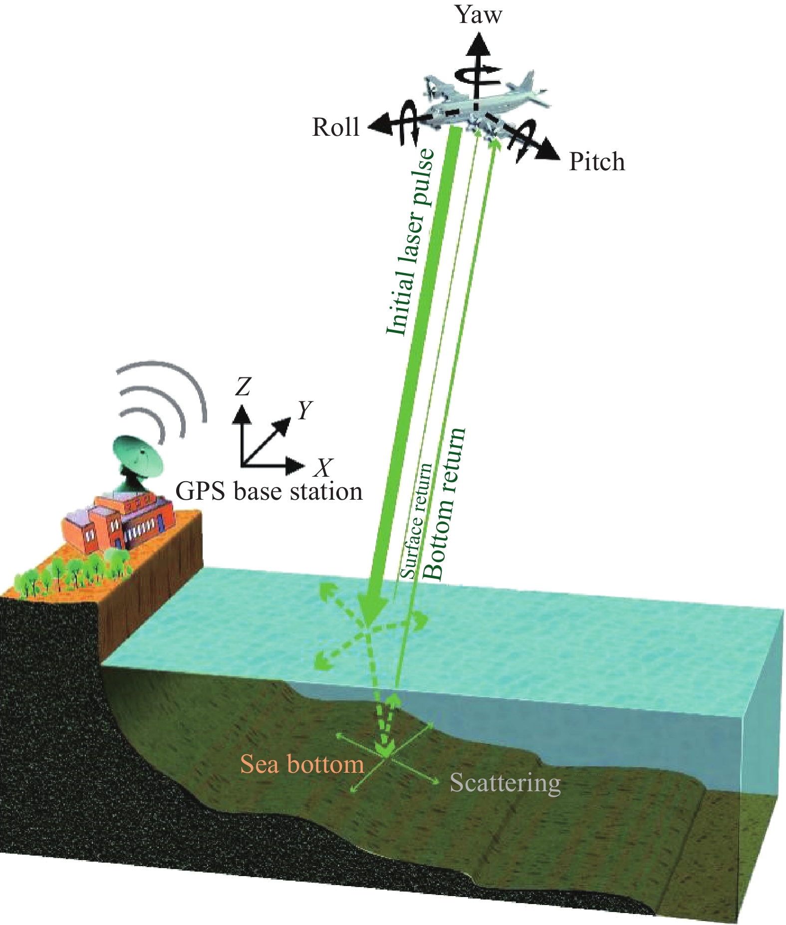
Fig. 1. Single frequency LiDAR sounding principle
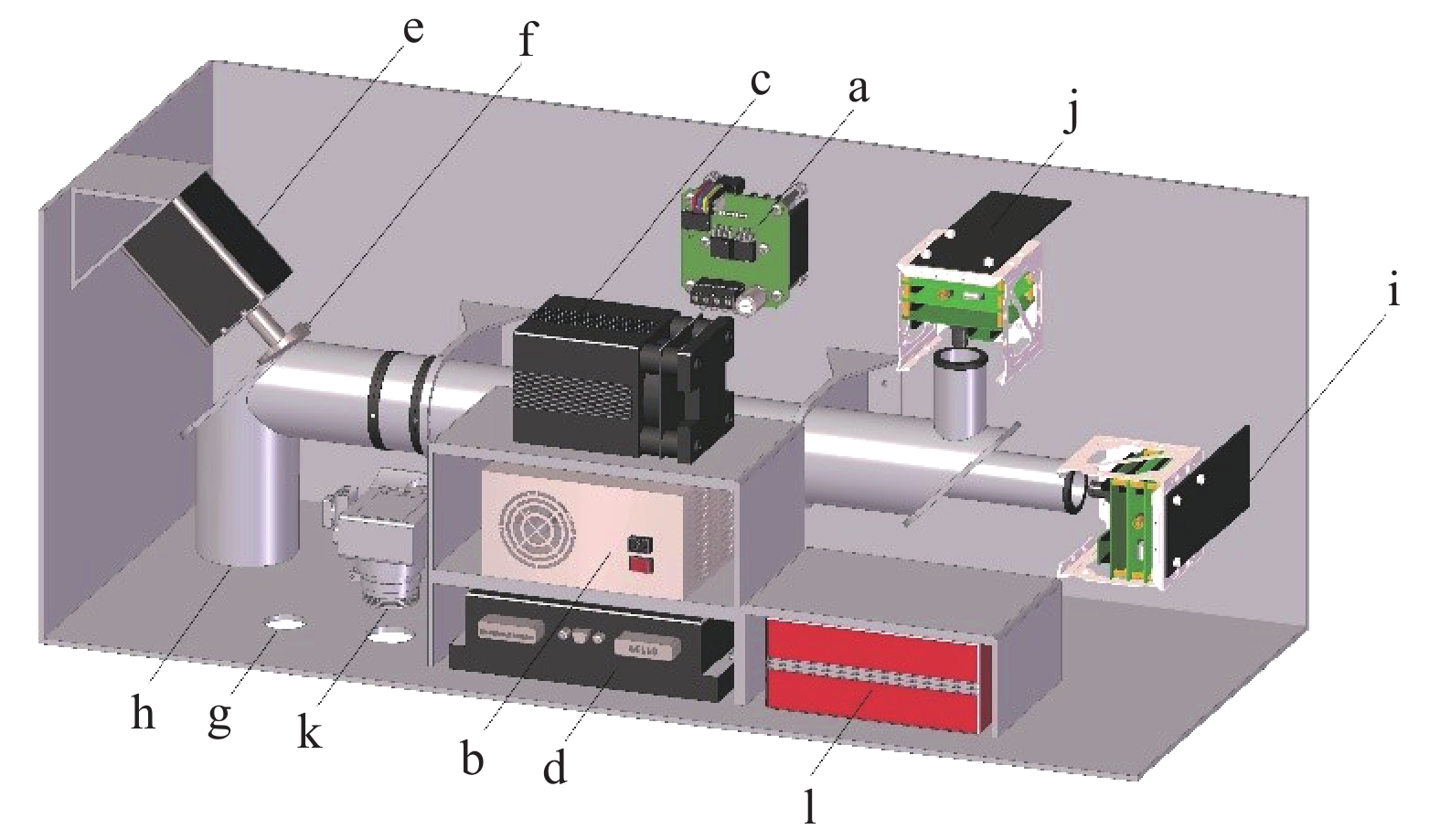
Fig. 2. System structure of LiDAR. a-Integrated control unit; b-Power supply; c-532 nm laser; d-Motor driver; e-24V DC servo motor; f-Reflective wedge; g-Optical emission channel; h-Optical receiving channel; i-APD and its processing circuit; j-PMT and its processing circuit; k-Area array multispectral high resolution CCD camera; l-POS system
Fig. 3. Zemax simulation reflection type wedge scanning unit
Fig. 4. Field loss factors corresponding to different water depths and receiving field of view
Fig. 5. Recognition factors for different water depths changing with field of view
Fig. 6. Recognition factor of 50 m water depth changing with field of view
Fig. 7. Structure of Kirk three-piece objective lens set
Fig. 8. Optical path of objective lens group
Fig. 9. MTF curve of objective lens group
Fig. 10. Improved Kenneth eyepiece structure
Fig. 11. Structure of PMT eyepiece group optical path
Fig. 12. Structure of APD eyepiece group optical path
Fig. 13. Optical path of LiDAR overall receiving telescope system
Fig. 14. Distribution of diffuse spots in each field of view
Fig. 15. Optical-mechanical system of LiDAR
Fig. 16. DC motor speed regulation circuit
Fig. 17. Schematic diagram of receiving and transmitting light system
Fig. 18. Grid scanning pattern
Fig. 19. Lissajous scanning pattern
Fig. 20. Lissajous optimal scan
Fig. 21. Measured waveform data
| Parts | Parameter | Value | | Laser | Wavelength | 532 nm | | Peak power | 100 kW | | Pulse width | 3 ns | | Repetition frequency | 1 kHz | | Divergence angle | 0.2 mrad | | Scanning unit | Wedge angle | 5º | | Wedge diameter | 40 mm | | Wedge thickness | 15 mm | | Angle between the bottom of wedge and vertical axis | 45º | | Motor speed | 540, 600 r/min | | Rated voltage of motor | 24 V | | Rated power of motor | 100 W | | Receiving Optical unit | Receiving field angle | 95 mrad | | Entrance pupil diameter | 82 mm | | Exit pupil diameter | 8 mm | | Magnification | 10.25× and 42× | | Bandwidth | ±1 nm | | Overall system | Weight | 25 kg | | Volume | 1050 mm×400 mm×
460 mm
| | Mode of delivery | UAV | | Flight speed | 0-10 m/s | | Flight height | 150 m | | Run time | 20 min | | Scanning width | 52.9 m | | Scanning point density | 1/m2 | | Best measuring depth | 25 m | | Maximum measuring depth | 50 m |
|
Table 1. [in Chinese]
| Parameters | Parameters name | Parameters values | Calculation formula(Parameters see column 1) | | θr | Equivalent receiving FOV | | θr=θr0cosθa/(ncosθw)
| | H | Equivalent flight height | 205.781
4 m
| H0=150 m
H=H0n(cosθw/cosθa)3 | | h | Water depth measurement | 25 m | | | m | Scattering angle mean cosine function | 8 | | | bf | Forward scattering coefficient | 0.4 | | | θw | Angle between laser direction and vertical direction | 6.74° | θa=10°
sinθa=nsinθw | | rr | Equivalent radius | 82.689 m
m
| rr0=82 mm
rr=rr0cosθw/cosθa | | rl | Equivalent radius of laser beam cross section | 3.054 m
m
| rl0=3 mm
rl=rl0cosθw/cosθa | | θl | Equivalent laser divergence angle | 0.1492 m
rad
| θl0=0.2 mrad
θl=θl0cosθa/(ncosθw)
| | n | Refractive | 1.333 | |
|
Table 2. [in Chinese]
| Value of qccoefficient
| Visibility range/km | | 1.6 | V>50
| | 1.3 | 10<V<50
| | 0.16 V+0.34 | 0.5<V<10
| | 0 | V<0.5
|
|
Table 3. [in Chinese]
| Lens | Radius of curvature/mm | Focal length/mm | Material | Refractive index (532 nm) | Distance | Surface/mm | | 1 | 198.543 | 213.098 | ZF14 | 1.9317 | 12 | air→ZF14 | | 2 | 600.383 | 644.395 | ZF14 | 1.9317 | 111.411 | ZF14→air | | 3 | −353.382 | −564.779 | F2HT | 1.6257 | 10 | air→F2HT | | 4 | 156.494 | 250.110 | F2HT | 1.6257 | 36.799 | F2HT→air | | 5 | 513.419 | 551.056 | ZF14 | 1.9317 | 12 | air→ZF14 | | 6 | −481.289 | 516.571 | ZF14 | 1.9317 | 307.790 | ZF14→air |
|
Table 4. [in Chinese]
| Lens | Radius of curvature/mm | Focal length/mm | Material/refractive (532 nm) | Distance to next side/mm | Surface | | 7 | $\infty $ | $\infty $ | SF66/1.937 5 | 8 | air→SF66 | | 8 | −135.530 | 144.565 | SF66/1.937 5 | 19.907 | SF66→air | | 9 | 48.617 | 51.858 | SF66/1.937 5 | 7.990 | air→SF66 | | 10 | 92.216 | −98.364 | SF66/1.937 5 | 16.1 | SF66→air | | 11 | 63.200 | 76.190 | LASF14A/1.829 5 | 10 | air→LASF14A | | 12 | −316.269 | −2 928.417 | LASF14A/1.829 5 | 7.6 | LASF14A→SF66 | | 13 | 143.183 | −152.728 | SF66/1.937 5 | 17.172 | SF66→air |
|
Table 5. [in Chinese]
| Lens | Radius of curvature/mm | Focal length/mm | Material / refractive (532 nm) | Distance to next side/mm | Surface | | 7 | $\infty $ | $\infty $ | SF66/1.937 5 | 4 | air→SF66 | | 8 | 41.854 | −44.644 | SF66/1.937 5 | 30.426 | SF66→air | | 9 | 52.443 | 55.939 | SF66/1.937 5 | 4.5 | air→SF66 | | 10 | −47.173 | 50.318 | SF66/1.937 5 | 1 | SF66→air | | 11 | 15.276 | 18.416 | LASF14A/1.829 5 | 7.5 | air→LASF14A | | 12 | −22.175 | −205.324 | LASF14A/1.829 5 | 4 | LASF14A→SF66 | | 13 | 19.558 | −20.862 | SF66/1.937 5 | 10.053 | SF66→air |
|
Table 6. [in Chinese]
| Lens | Optical transmittance | Surface | | Objective 1 | 89.9% | air→ZF14 | | Objective 2 | 89.9% | ZF14→air | | Objective 3 | 94.32% | air→F2HT | | Objective 4 | 94.32% | F2HT→air | | Objective 5 | 89.9% | air→ZF14 | | Objective 6 | 89.9% | ZF14→air | | Eyepiece 7 | 89.8% | air→SF66 | | Eyepiece 8 | 89.8% | SF66→air | | Eyepiece 9 | 89.8% | air→SF66 | | Eyepiece 10 | 89.8% | SF66→air | | Eyepiece 11 | 91.41% | air→LASF14A | | Eyepiece 12 | 99.9% | LASF14A→SF66 | | Eyepiece 13 | 89.8% | SF66→air |
|
Table 7. [in Chinese]
| Component | Weight/kg | | Power source | 5 | | 532 nm laser | 3 | | 80 flange servo motor | 0.75 | | Motor driver | 0.75 | | Optical pipeline | 2.1(7 series aluminum) | | APD or PMT and its circuit | 0.5 | | IMU | 2.6 | | Integrated control system | 3.5 | | CCD camera | 0.35 | | Other | 0.95 | | Outsourcing network | 5 (PVC) | | Total | 25 |
|
Table 8. [in Chinese]
| Component | Volume/mm3 | | Power source | 188×156×97.5 | | 532 nm laser | 104×104×166.5 | | 80 flange servo motor | 100×60×70 | | Motor driver | 150×100×40 | | Optical pipeline | 80(inside diameter)×660 | | IMU | 200×116×80 | | Integrated control system | 180×120×100 | | Outsourcing network | 1 050×460×400 |
|
Table 9. [in Chinese]
| Plan | Order number | Flight speed/m·s−1 | Flight height/m | Scanning point density/m−2 | Scanning width/m | Distance/m | Area/m2 | | 1 | a | 6 | 100 | 2.42 | 35.26 | 36 | 1 269.36 | | b | 8 | 100 | 2.07 | 35.26 | 48 | 1 692.48 | | c | 10 | 100 | 1.81 | 35.26 | 60 | 2 137.20 | | 2 | a | 6 | 150 | 1.29 | 52.89 | 36 | 1 904.04 | | b | 8 | 150 | 1.14 | 52.89 | 48 | 2 538.72 | | c | 10 | 150 | 1.02 | 52.89 | 60 | 3 173.40 | | 3 | a | 6 | 200 | 0.81 | 70.53 | 36 | 2 539.08 | | b | 8 | 200 | 0.73 | 70.53 | 48 | 3 385.44 | | c | 10 | 200 | 0.66 | 70.53 | 60 | 4231.80 |
|
Table 10. [in Chinese]