
Han Yin, Yingxiong Song, Yingchun Li, Song Chen, Yetian Huang. Free-Space Optical Communication Atmospheric Turbulence Compensation Based on Multiple Input Multiple Output Mode Diversity Coherent Reception[J]. Chinese Journal of Lasers, 2022, 49(23): 2306002
- Chinese Journal of Lasers
- Vol. 49, Issue 23, 2306002 (2022)
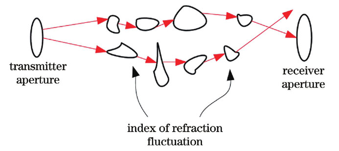
Fig. 1. Schematic of atmospheric refractive index fluctuation
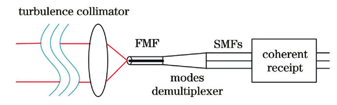
Fig. 2. Modeling schematic for few-mode fiber (FMF) collection of free space optical communication (FSO) beam
Fig. 3. Schematic of simulation system
Fig. 4. Offline processing steps based on LMS-MIMO algorithm
Fig. 5. LMS-MIMO adaptive equalizer structure diagram
Fig. 6. Constellation of X-polarization with one mode compensation when
Fig. 7. Constellation of Y-polarization with one mode compensation when
Fig. 8. Constellation of X-polarization with three modes compensation when
Fig. 9. Constellation of Y-polarization with three modes compensation when
Fig. 10. Constellation of X-polarization with one mode compensation when
Fig. 11. Constellation of Y-polarization with one mode compensation when
Fig. 12. Constellation of X-polarization with three modes compensation when
Fig. 13. Constellation of Y-polarization with three modes compensation when
Fig. 14. Relation diagram of optical signal-to-noise ratio (OSNR) and bit error rate (BER) when
Fig. 15. Relation diagram of OSNR and BER when
Fig. 16. Relation diagram of OSNR and BER when
|
Table 1. Parameters in simulation experiment
|
Table 2. Refractive index structure parameters of atmospheric turbulence in simulation experiment

Set citation alerts for the article
Please enter your email address
© Copyright 2018-2021 | Chinese Laser Press. All Rights Reserved 沪ICP备15018463号-20