Huixin Zhang, Lishuang Feng, Yulong Hou, Shan Su, Jia Liu, Wenyi Liu, Jun Liu, Jijun Xiong. Preparation and characterization of a liquid level sensor based on plastic fibers[J]. Chinese Optics Letters, 2015, 13(8): 080601
Copy Citation Text
Preparation and characterization of a liquid level sensor based on macro-bending coupling of fibers are demonstrated in this Letter. The sensitive component can be obtained through a twisting and twining structure of transparent cladding plastic fibers. The difference in light power originating from the surrounding media in the fibers is tested. The light power loss for different tested media and the fiber bending magnitude are investigated. The sensing measurements show that the coupling light power in the passive fiber decreases in accordance with increasing liquid level, whereas it exhibits a steady tendency in the case of the active fiber.
Owing to the advantages of small size, high sensitivity, and better security, fiber sensing technologies have been extensively applied in various sensors and actuators such as adaptive optical equipment, pressure and acoustic transducers, liquid level measuring sensors, and image processing components[1–7]. At present, many liquid level testing sensors utilize the variation of light path generated by the optical signal of the fibers via the liquid media to sense the change of liquid level[8]. Typically, the liquid level sensing structures of the optical fiber have a reflecting mirror surface on the sensitive part, which is in accordance with the principle of total reflection of the optical signal. When the reflecting mirror surface is in contact with different liquid media, the restrained total internal reflection is triggered by the refractive index of the media, and the change in liquid level can be acquired by testing the output signal variation of the reflected light signal[9,10]. However, sophisticated sensing components, such as the reflecting mirror surface and so on, require complex microfabrication procedures, and even a slight difference in the component structure will noticeably influence the testing results[11]. Nevertheless, the sensitive principle of these sensors can be applied extensively by modifying the transmission media of light path. Furthermore, as long as the transmission media can effectively influence the optical signals, such as in the case of intertwined twisted-pair fibers with a lucid cladding as the sensitive part, the magnitude of the media can also be calculated[12]. Compared with the use of component structures whose sensitive part is micromachined to achieve the light path suppression function, the method of sensing the surrounding media by the fiber itself appears more simple and convenient. The optical signal energy transmitted with the cladding model in the fibers may be easily changed by the variation of the medium refractive index[13]. In this Letter, the investigated structure possesses the advantage of continuously sensing the tested liquid level, and the cladding model is employed as the leading plan for light transmission, showing a high sensitivity to the surrounding media. The influence of different twining models on the sensitivity of the sensors is verified. We estimate the sensing and response of intertwined twisted-pair fibers with a lucid cladding by measuring the level of a liquid medium. Furthermore, the proposed structure is compared with the conventional testing methods where the energy value of the optical signal varies in accordance with the change of the medium.
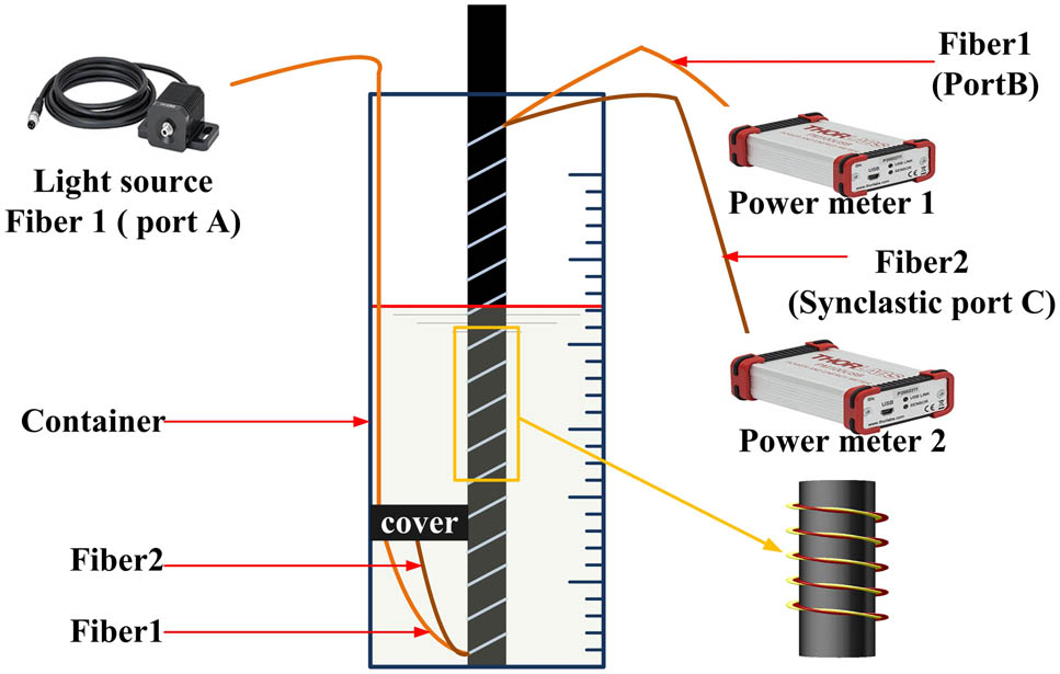
As shown in Fig. 1, the measurement system was prepared by using a plastic fiber, a polyamide stick basement, a 660 nm LED (Thorlabs, M660F1), an optical power meter (Thorlabs, PM100USB), and a container for the liquid. The twisted-pair plastic fiber with a diameter of 980 μm is twined on the polyamide stick basement, and the initial twining screw pitch is 2.3 mm. The twisting model of the plastic fiber can increase the contact area of the pair of fibers, ensuring that the light energy in the active fiber sufficiently radiates into the passive fiber and the optical signal in the passive fiber is transferred along two directions in the cladding model. The twined structure of the fiber on the polyamide stick raises the macrobending loss magnitude of the optical signal from the active fiber to the outside. All the experiments are conducted in a graduated container with the tested liquid. The corresponding ports of the liquid level sensing fibers are connected to the LED light source (14.5 mW) and optical power meters, and then the polyamide stick basement twined with the twisted-pair fiber is placed into the container. The output information from the optical power meters, recorded in real time, is stored in a computer for the subsequent data processing. The optical signal is cast from Port A of the active fiber, and the output light power is measured on the output ends of the active and passive fibers through the transmission in the light path of the pair of fibers. For portability and robustness, the sensor is equipped with a polyamide stick basement whose diameter is 26 mm. The schematic diagram of the testing equipment is illustrated in Fig. 1. The sensitivity and performing effects of the system are tested based on the aforementioned structure.
Figure 1.Schematic diagram of the proposed measurement system.
The optical signal output power was measured by the optical power meters. The output power value at the output Port B of the active fiber was tested. The minimum resolution of the optical power meter is 0.1 nW. The testing results, shown in Fig. 2, reveal that the optical signal, which transmits mainly by the fiber core model in the active fiber, exhibits a noticeable change of the output power value for different numbers of twining circles.
Sign up for Chinese Optics Letters TOC. Get the latest issue of Chinese Optics Letters delivered right to you!Sign up now
Figure 2.Coupling power and output power for different twining circles.
This can be attributed to Eq. (1) where and represent the phase velocity at the fiber axis and at the position to the bending center, respectively; is the bending radius of the fiber. Equation (1) defines the constraint limit of the power in the guided model. The excess portion will transfer out of the light path as energy loss. That is, the energy loss will increase when the bending part of the light transmission path increases[14].
The light power emitted from the active fiber will couple into the passive fiber as scattered light. The main coupling processes include the space coupling and the transmission coupling on the interface of the fibers. The coupling ratio of the space coupling is expressed as where is the largest angle of incidence of the received scattered light in the passive fiber, and coupling ratio of the space coupling is given by where is the surface transmissivity of the passive fiber, and is the fiber core–cladding transmissivity of the passive fiber[12]. As the light path emitted from the active fiber cladding is complex, Eqs. (2) and (3) are all deduced from a point light source of the active fiber. Further extending to the whole fiber cladding, the coupling light signal may be considered approximately as the superposition of several point light sources. Therefore, it can be estimated that the synclastic coupling Port C of the passive fiber will receive increased light power, along with the increase of the light spot of the acceptable scattered light, which comes from the increase in the number of twining circles of the two fibers.
In accordance with this principle, the output power is tested at the synclastic coupling Port C of the passive fiber while changing the number of circles of fiber twining. As described in Fig. 2, the passive fiber receives energy of radiant light because of the fiber bending. In accordance with the aforementioned coupling theory of light, it can be observed that, compared with the case in which they are straight, the fibers intertwined with three circles exhibit an improvement in the tested power values.
The bending circles also affect the power loss in the passive fiber. When increasing the number of twining circles, the power loss in the passive fiber becomes higher than the coupling light power from the active fiber. As shown in Fig. 2, attenuation in the tested light power can be observed when the fibers twine with the number of circles between 7 and 15. Notably, not all the lost energy from the active fiber radiates into the passive fiber, and therefore the magnitude of the power in the passive fiber is lower than that of the power in the active fiber (Fig. 2). The results suggest that the energy variation of the optical signal can be effectively controlled by properly selecting the fiber pair material and accurately designing their structure.
The light energy radiated into the passive fiber is transmitted mainly through the cladding model, and the role of the evanescent field is dominant. When the medium around the fibers changes, for example from air to water, the refractive index varies from 1 to 1.33. The equation [Eq. (4)] to calculate the angle of total reflection is given by where and are the refractive indices of the fiber cladding and the medium, respectively; and is the angle of total reflection. When the refractive index of the medium increases, the critical angle of the total internal reflection decreases in the cladding of the passive fiber. Thus, a stronger light signal will be generated with an angle of incidence higher than the angle of total reflection. Additionally, a greater portion of the light signal will be refracted into the medium, thus generating the loss of the light power. The magnitude of the loss also increases with the increase of the medium around the fibers. Owing to the role of the evanescent field, the effect on the light transmission can be examined by changing the medium of the passive fiber; namely, changing the medium refractive index in the evanescent field[13]. Therefore, the media will affect the light transmission with the cladding model by changing the medium in the container. Noticeably, the magnitude difference of the sensitive section surrounded by the media will determine the degree of light energy being affected[15]. The power outputs of twined twisted-pair plastic fibers in different media with the same contacting volume, or the same medium with different contacting volume, are shown in Fig. 3. The output power will vary if the medium surrounding the fiber is different, and the difference depends on the refractive index of the medium. The light power loss is proportional to the degree of contact between the sensing part and the medium. This result can be compared with the findings from previous reports[12,16–18]. All of the testing methods mentioned in these studies use the basic theory of influencing the transmitted light power by changing the liquid level.
Figure 3.Coupling power in different media and for different contacting volumes.
Figure 3 shows the relation between the liquid level variation and the value of the output power of the sensing component at the active fiber output Port B [Fig. 4(a)], and that at the passive fiber synclastic coupling Port C [Fig. 4(b)]. Water is used as the medium in our work. The results show that the output power at Port B remains almost unchanged because the signal-to-noise (SNR) ratio is low, whereas the output power at Port C exhibits a linear variation when the liquid level changes. The output curve of Port C is fitted by the least-squares method, which demonstrates that the sensing component exhibits an excellent linear relationship, which is favorable enough to be exploited.
Figure 4.(a) Relation between output power and liquid level; (b) relation between coupling power and liquid level.
In accordance with the slope of the coupling characteristic in Fig. 4(b), it can be calculated that the sensitivity of the liquid level sensor is . The minimum resolution of the optical power meter used in this sensor is 0.1 nW. Thus, the sensor is sensitive enough to test the change of the liquid level.
There are many elements that affect the accuracy of the sensors. The theoretical accuracy of the liquid level sensor is 0.125 mm in accordance with the minimum resolution of the optical power meter (0.1 nW). However, the real testing accuracy cannot achieve the theoretical accuracy because of the presence of complex environmental elements such as the visible light, the tested medium, and so on. The accuracy value of the liquid level sensor presented in this Letter is , which is the maximum error obtained by comparing multiple testing results with the results calculated by fitting the curve.
Besides the environmental factors, the temperature is an important aspect that must be considered in the practical design of sensors. For the liquid level sensor present in this Letter, the temperature can cause testing errors in the results. To evaluate the thermal effect on the liquid level sensor, the testing results for the same liquid level were compared at different temperatures. As the refractive index of the tested medium and the internal performance parameters of the fibers generate different degrees of change at different temperatures, large deviations can be observed in the testing results (Fig. 5). To obtain accurate testing results from the liquid level sensors, it is necessary to perform a calibration of the sensors at different temperatures. Follow-up work will lay emphasis on the study of thermal effects on the liquid level sensors.
In conclusion, a liquid level sensing and actuating system consisting of twined twisted-pair plastic fibers is demonstrated in this Letter. The sensitive component of the system consists of plastic fibers with a readily modified shape. The change of the medium surrounding the sensitive component produces significant effects on the power value of the light transmitted, mainly with the cladding model in the passive fiber. As the contact between the sensitive component and the medium changes when the number of twining circles is different, a variation of the sensitivity can be observed. Our work shows that the power at the synclastic coupling port of the passive fiber exhibits a linear variation in accordance with the liquid level, which can therefore be effectively detected. Thus, the different liquid levels of the tested medium can be effectively sensed by precisely controlling the physical interface of the light transmission path. The model could be applied to construct sensors to measure liquid levels in a simple way, yet still retain a high sensitivity.
Huixin Zhang, Lishuang Feng, Yulong Hou, Shan Su, Jia Liu, Wenyi Liu, Jun Liu, Jijun Xiong. Preparation and characterization of a liquid level sensor based on plastic fibers[J]. Chinese Optics Letters, 2015, 13(8): 080601