Orbital angular momentum (OAM) of an optical vortex has attracted great interest from the scientific community due to its significant values in high-capacity optical communications such as mode or wavelength division multiplexer/demultiplexer. Although several configurations have been developed to demultiplex an optical vortex, the multiwavelength high-order optical vortex (HOOV) demultiplexer remains elusive due to lack of effective control technologies. In this study, we present the design, fabrication, and test of metasurface optical elements for multiwavelength HOOV demultiplexing based on optical gyrator transformation transformations in the visible light range. Its realization in a metasurface form enables the combined measurement of OAM, the radial index p, and wavelength using a single optical component. Each wavelength channel HOOV can be independently converted to a high-order Hermitian–Gaussian beam mode, and each of the OAM beams is demultiplexed at the converter output. Furthermore, we extend the scheme to realize encoding of the three-digit gray code by controlling the wavelength or polarization state. Experimental results obtained at three wavelengths in the visible band exhibit good agreement with the numerical modeling. With the merits of ultracompact device size, simple optical configuration, and HOOV recognition ability, our approach may provide great potential applications in photonic integrated devices and systems for high-capacity and demultiplex-channel OAM communication.
In the past few decades, since Allen et al. pointed out that a light beam with a helical phase factor carries orbital angular momentum (OAM), the study of optical modes beams has become extremely important in the field of photonics.1–3 The OAM beam has attracted immense interests for its unique characteristics and applications.4 In particular, in information and communication technology, OAM has probably opened some of the most promising fields of application, offering a wider state space for enhanced-capacity transmission and high-alphabet quantum protocols.5–8 For most of these applications, the determination of OAM in advance is important and necessary. The need to measure OAM has promoted the development of many methods and techniques with different levels of complexity and performance.9–17
Sign up for Advanced Photonics Nexus TOC. Get the latest issue of Advanced Photonics Nexus delivered right to you!Sign up now
Generally, the generated optical vortex beam can then transmit either in specific vortex fiber or in free-space, and finally the OAM information is demultiplexed.18,19 Mostly, for the detection of a given OAM value, researchers have presented many methods to detect OAM states.20 One common way to identify the topological charge is to directly observe the interference or far-field diffraction intensity patterns.21–23 But, these methods applied only to the detection of the azimuthal index . The interference or diffraction patterns could be indistinguishable in the high-order optical vortex (HOOV).24 In particular, for HOOV, the Laguerre–Gaussian (LG) modes form a complete and orthonormal basis and are described by a radial index and an OAM azimuthal index .25 Consequently, detection of the radial and azimuthal of HOOV beams simultaneously and precisely is of vital significance for further increasing the optical communication modes system capacity.26 Up to now, many effective methods have been proposed to measure the and , which mainly include astigmatism or mode converters27–31 and special diffraction gratings.32,33 All the aforementioned methods have significant disadvantages. Among these, holographic amplitude-masking techniques modulating the amplitude and phase of a beam using a phase-only spatial light modulator (SLM), although lossy, have become a useful experimental tool to measure any arbitrary desired optical vortex modes. However, these traditional methods of OAM detection are based on large-sized optical devices such as SLM or cylindrical pair, which are only suitable for large communication systems rather than the integrated lab-on-chip systems, resulting in a low modulation rate and poor integration. Therefore, to address this problem, the research of a chip-level OAM detection device has become a hotspot. Recently, with the appearance of on-chip nanostructures or metasurfaces, compact OAM detection strategies have been proposed, exhibiting additional merits of miniaturization and enhanced functionality.34–37 Undoubtedly, these methods provide new routes to detect the input OAM modes (), however they do not simultaneously measure both radial and azimuthal . Therefore, how to detect the HOOV mode becomes a task of great importance.
To cope with this problem, in this study, we propose a smart and powerful method of optical integration based on the optical metasurface to detect HOOV. The broadband response of the designed metasurface will achieve the wavelength demultiplexing. The core of the HOOV detection technique is mainly based on the use of a saddle-shaped phase (SSP). By superposing the optical vortex phase and SSP, the designed gyrator transformation (GT) metasurface can transform the Gaussian beam into high-order Hermitian–Gaussian beam (HOHG). In this manner, we are able to obtain both the azimuthal index and the radial index () of each wavelength HOOV component within our state–space. In addition, our technique enables us to achieve the optical coding of the gray code of a three-wavelength state in the natural basis of detection . The detection efficience for multiwavelength HOOV is 100%, and the polarization conversion efficiencies of the GT metasurface are larger than 87.9%. Our method provides an efficient method for multiwavlength HOOV demultiplexing, which is expected to pave the way for high capacity and high efficiency optical communication applications.38
2 Design and Simulation
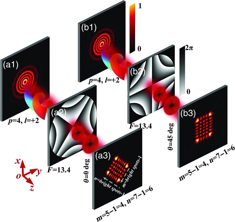
Here, we will discuss how to determine the mode indices of an HOOV. Based on the optical mode transformation of to , researchers proposed the GT-based OAM detection scheme for the vortex optical beam. We have investigated the double cylinder lenses model, which provides a kernel function for astigmatic mode converter conversion between HOOV and HOHG modes.39 The mode conversion is in the category of GT, which is physically explained by Rodrigo et al.40–43 The schematic diagram of mode indices measurement of with SSP is shown as Figs. 1(a1)–1(a3). To validate that SSP can achieve detection HOOV, the modes of the optical field of with beam waist are performed. After GT, the complex amplitude of the output field in the far-field is:
Figure 1.Schematic of mode detection HOOV mode is chosen as an example. (a1) Intensity distribution of HOOV beam of . (a2) SSP with and . (a3) Intensity distribution of HOHG . (b1) HOOV . (b2) SSP with and . (b3) Intensity distribution of HOHG after rotating 45 deg. The subscripts and are the mode numbers of and . The subscript indicates the modulation parameters of SSP. The SSP range of the , coordinate is and , respectively.
In Eq. (1), represents the incident complex amplitude. represents the phase of the GT kernel function. The intensity distributions of the detection output modes are shown as Fig. 1(a3), where the number and orientation of diffraction bright spots provide the information of the radial and azimuthal mode indices of HOOV. Meanwhile, the mode number relationship is (, ) and (the upper left orientation of diffraction bright spots signify positive, and the upper right signify negative) in GT of and , where and are two integer indices to describe the mode . and are two integer transverse indices to describe the mode .44
Here, the kernel function can be through the geometrical optical analysis of the orthogonal double cylindrical lens (see Supplementary Material, Sec. 1). The kernel function is called the SSP or hyperbolic phase. The SSP performs mode conversion between the LG and HG modes. The phase distribution of the proposed SSP is expressed as: where are the Cartesian coordinates of the SSP. denotes a coefficient related to the refractive index of air and the spherical cap radius of the cylindrical lens. is the rotation angle of the SSP.45 and are the most critical parameters of the SSP. According to physical optics, the focal length of the cylindrical lens is . is the refractive index of the lens. The mode-matching condition is .46 Therefore, can be further expressed as . For the constant mode incidence, the initial beam waist is a certain value. determines the number of equivalent phase lines of the SSP. The two-dimensional (2D) phase distribution of the SSP with (the initial beam waist is 0.3 mm, is the vacuum, and is the glass) and the rotation angles and are shown in Figs. 1(a2) and 1(b2). For the 2D SSP distribution with different F and 3D SSP, one can find that in Sec. 2 of the Supplementary Material.
Figure 2.Design and fabrication of geometric metasurface. (a)–(e) Process of the phase superposition. (a) Phase distribution of the incident field corresponds to Fig. 1(a1). Symbol + indicates phase superposition. (b) SSP with and corresponds to Fig. 1(a2). The sign → indicates the result phase superposition. (c) Phase distribution of corresponds to the phase of Fig. 1(a3). (d) Blazed grating phase with the period . (e) Metasurface phase. (f) Unit cell of metasurface and the structural parameters. () 3D view of nanorods. Length , width , height , and period . Top view of the nanorods corresponds to four characteristic phase rotation angles (180 deg), 46.8, 83.6, and 105.3 deg. The red plus sign + indicates the center of the structure. (g) Phase value of the four characteristic corners of the nanorods at the corresponding design wavelengths of 405, 532, and 633 nm. Color corresponds to the corresponding wavelength. (h) Metasurface device corresponding to phase diagram (e). Optical microscope image of the metasurface with a radius of (Olympus objective, magnification , numerical aperture , ). The red dotted frame shows a partially enlarged view of the central phase optical microscope image (Olympus objective, magnification , numerical aperture ). Plus sign + indicates the center of the metasurface corresponding to (f) symbol +.
As shown in Figs. 1(a1)–1(a3), we proposed precise detection from to through the precise parameter F modulation of SSP. The generated , is shown in Fig. 1(a3).47 The direction of the HG mode in the upper left direction corresponds to the positive topological charge of the mode, and vice versa. As shown in Figs. 1(b1)–1(b3), the rotation of the detection optical field is determined by the rotation angle of SSP. In Fig. 1(b2), SSP rotating 45-deg counterclockwise corresponds to Fig. 1(a1). For a determined , the 2D relative spatial distribution of SSP is unchanged for different rotation angle . Their spatial distribution is revolving for different , which does not affect the numbers of mode index and . Therefore, Fig. 1(b3) of clockwise rotating 45 deg corresponds to Fig. 1(a3). In the Supplementary Material, Sec. 3, we analyze the GT of the modes detection in various . Next, consisting of artificially engineered nanostructures, the metasurface is generally used in various functional optical devices to manipulate the optical beam in almost any arbitrary manner. Here, we design and fabricate a metasurface that is applied to detect . To facilitate the experiment and reduce the registration error during the experiment, we fabricated a single metasurface device through the principle of phase superposition to demonstrate the detection capability of SSP. The design physical device of the HOOV detection metasurface is shown in Fig. 2, which realizes the modulation function of Figs. 1(a1)–1(a3).
3 Results and Discussion
The phase of the design metasurface phase is shown in Figs. 2(a)–2(e). In the design, the phase superposition and phase shift are applied to realize the metasurface phase distribution.
As shown in Fig. 2(a), the phase distribution of the beam can be written as
In polar coordinates, indicates a complex angle. is the complex amplitude of the incident beam corresponding to Fig. 1(a1). The coefficient is ( is the Kronecker delta function). is the generalized Laguerre polynomial. is the beam waist. is the wave number, and is the beam complex parameter in the beam waist plane ( is the beam’s Rayleigh distance).48 By superimposing the phase in Fig. 2(a) and the SSP phase in Fig. 2(b), we can obtain the phase , which is shown in Fig. 2(c). represents the conversion of Cartesian coordinates to polar coordinates. In the design, a linear phase is introduced to separate the target detection optical field from the zeroth-order diffractive field. In Fig. 2(d), the period of the blazed phase grating is , which is applied as linear phase. The phase of the grating is expressed as
Figure 3.Experimental results of multiwavelength HOOV detection. (a) Schematic of optical field diffraction of the metasurface. Three wavelengths , , and combined optical incident with left-handed circular polarization. The dotted line corresponds to wavelength color. Three-color sample drawing villains represent the photons of three wavelengths. is the diffraction angle at three wavelengths. The target detection field appears at three different diffraction azimuths , , and , which accompany a right-handed circular polarization state. (a1)–(a3) Diffraction field of the target detection field at three wavelengths. (a1) Detection diffraction field at the design wavelength . (a2) Diffraction field at . (a3) Diffraction field at . The Cartesian coordinate system is represented by the black dotted line with a single arrow. The red solid arrow line indicates the axis direction. The dotted line double arrow indicates the position of the target detection field on the CCD. (b) Simulated polarization transformation efficiency of metasurface in the visible light band (from 400 to 700 nm) and the experimental measured data points at three wavelengths , , and . The black solid line is the calculated data for the entire visible band. The circular data points are the calculated values at three wavelengths. Triangular data points are the experimental data (color corresponds to wavelength). (c) Gray code pattern based on metasurface detection mode with three-wavelength switches. (c1)–(c8) Gray code images 111, 110, 101, 011, 100, 010, 001, and 000 corresponding to binary numbers 5, 4, 6, 2, 7, 3, 1, and 0, respectively. The white number group is the gray code array. Cyan numbers are binary numbers. The colored circular arrow curve indicates the polarization state of the corresponding wavelength.
As shown in Fig. 2(e), the final phase distribution of the metasurface is . Actually, our proposed design method can also be applied to popularize an arbitrary HOOV detection. Obviously, the three disperate phase elements can be achieved by one metasurface. Therefore, the system is more simple and compact.
Furthermore, the designed phase distribution can be realized by a metasurface based on Pancharatnam–Berry phase modulation. For the design wavelength of 405 nm, a metasurface device with a nanorods unit will realize the phase of Fig. 2(e).49,50 In Fig. 2(f0), the length, width, height, and period of the nanorod is , , , and , respectively. As shown in Figs. 2(f1)–2(f4), the rotation angles of the four selected nanorods are , 46.8, 83.6, and 105.3 deg about the metasurface center. The modulation phase values of the four selected rotation angles are represented by the height of the purple pyramid in Fig. 2(g). The corresponding phase values are approximately equal to , , , and , respectively. Meanwhile, because the metasurface is the broadband response, we also calculated the phase modulation beyond the design wavelength of 405 nm. In Fig. 2(g), the green pyramid represents the phase modulation value for the wavelength of 532 nm. The red pyramids indicate the phase modulation values for the wavelength of 633 nm. In this way, the detection HOOV of multiwavelength broadband can be realized. Moreover, the polarization conversion efficiency for a single nanorod and the phase modulation relationship corresponding to the entire phase rotation angle are in Sec. 4 of the Supplementary Material. Figure 2(h) is the optical microscopy image of the metasurface. The diameter of the metasurface is . The red dotted frame shows the partial enlarged image, and the red cross shows the center position. From the overall optical image and the partial enlarged image, the phase structure is consistent with the calculated phase structure in Fig. 2(e), especially at the center position related to the mode number . The fabrication process of the metasurface is the same as that in our previous works.51 The actual photo of the metasurface is in the Supplementary Material, Sec. 5.
Figure 4.Schematic diagram of the experimental setup.
As shown in Fig. 3, we perform the optical experiments of the metasurface. Figure 3(a) shows the schematic diagram of the optical path. The experimental optical path is displayed in the methods. Firstly, the combined three left-handed circularly polarized beams are incident with wavelengths , , and , respectively. The combined three-wavelength optical beam is diffracted by the metasurface and generates the right-handed circularly polarized optical beam . The target field is located in (). The observed results are in excellent agreement with the simulation shown in Figs. 1(a1)–1(a3). The number of the bright spots minus one gives the magnitude of the azimuthal index , and the sign of can be determined easily by investigating the orientation of these spots. The diffraction angle relationship is , () followed by target detection fields of different wavelengths.52 Hence, the different wavelength HOOV can be effectively separated by the designed metasurface. As shown in Fig. 3(a1), it is the detection optical field of at the design wavelength of 405 nm. The diffraction angle is , and the detection pattern is consistent with that simulated in Figs. 1(a1)–1(a3). For the wavelengths of 532 and 633 nm, they are shown in Figs. 3(a2) and 3(a3). Obviously, our metasurface can be effectively separated by demultiplexing multiwavelength HOOV in the space. As shown in Fig. 3(b), to further discuss the characteristics of the metasurface, the polarization conversion efficiency reflecting the capacity of the basic cells for manipulating the light in the local area, which is defined as , is employed to evaluate the performance of the designed metasurface. The black solid curve represents the calculated, which is the different polarization conversion efficiency between the 400- and 700-nm wavelengths. For the three experimental wavelengths, the corresponding colored triangles are the experimental results, and the blue circles are the simulation results. The maximal polarization conversion efficiency of the detection HOOV metasurface is as large as 87.9% at the design wavelength of 405 nm. For the wavelengths of 532 and 633 nm, the conversion efficiency is about 46.9% and 24.9%, respectively.
As described above, multiplexing and demultiplexing technology is considered to be the most potential future large-capacity communications solution. Here, we study the output field located in a different position that can be considered for information encoding with different wavelengths. The gray code is one extremely important encoding method due to its convenience and reliable characters of minimization error.38,53 As shown in Fig. 3(c), our diffracted optical field by the metasurface can be applied to encode to achieve the three-digit gray code by controlling the wavelength or polarization state. In this study, the code is “1” when the detection optical field appears, and it is “0” when it does not appear. For example, in Fig. 3(c2), the “110” gray code can be achieved by turning off the incident red light wavelength. Other coding patterns can be achieved by selecting a combination of three wavelengths. As shown in Figs. 3(c1)–3(c8), the corresponding gray codes are “111,” “110,” “101,” “011,” “100,” “010,” “001,” and “000.” Cyan numbers are the binary code numbers corresponding to Figs. 3(c1)–3(c8) gray code, which are “5,” “4,” “6,” “2,” “7,” “3,” “1,” “0.” It is worthy to note that turning on/off the wavelength is the simplest and most effective coding method, but, in fact, we can also control the polarization state of the incident optical to achieve the gray code encoding. The polarizers or radial polarization converters can be used to achieve real-time polarization control of the incident field. For example, as shown in Fig. 3(c3), the gray code of “101” is realized, and the solid circular line with the color arrow represents the right-handed circular polarization. In other words, only for the left-handed circularly polarized incident field, the coding target field will appear by the metasurface. Here, we only demonstrate the coding based on the right-handed circular polarization. Actually, the encoding of different polarization states can also be realized based on the metasurface because different polarization states correspond to different intensity encoding, which will greatly expand the amount of encoded data.
4 Experimental Methods
As shown in Fig. 4, the experimental system was built to realize the proposed detection optical field and gray code. A fiber-laser (Fiblaser 405 nm) with wavelength and the two solid-state lasers (MGL-III-532/633–500 mW) with wavelength and were selected as the light source. Three visible light waveband (from 400 to 700 nm) beam expander collimators were used to expand and collimate the three (405, 532, and 633 nm) laser beams. Three linear polarizers were used to realize the polarization of the three laser beams. Three 5/5 beam splitters were used to combine three-wavelength laser beams. The three apertures were used to ensure the quality of the linearly polarized beam and adjust the diameter of the laser beam. The three polarizers were used for the detection of the linear polarization state of the three-wavelength laser beams after the small aperture diaphragm. The quarter-wave plate was used to convert the three-wavelength combined linear polarization state laser into a circular polarization state. The combined three-wavelength laser was modulated into left-handed circularly polarized light and then together through the modulation unit of the metasurface device. Finally, the generated optical field was captured by a CCD camera (DFK 33U×174, Sony IMX174LQJ-C , pixel pitch , target surface size 1/1.2 in.). In the process of combining three-wavelength lasers, the red light entering the optical path was modulated by three splitters when they arrive at the metasurface modulation unit. The green light entering the optical path was located through the action of the beam splitter twice. The blue-violet light directly entered the metasurface modulation unit through the beam splitter. We can also select different combined optical paths for light-field testing. Numbers 1), 2), and 3) are the planes that indicate the movement of the quarter-wave plate, the metasurface device, and CCD along the axis direction. The red dotted arrow is the coordinate . Sec. 6 of the Supplementary Material has an actual optical path picture.
5 Conclusions
We propose a method for multiwavelength HOOV demultiplexing and coding based on a dielectric metasurface. The metasurface for HOOV detection is designed and investigated in detail. The performances of the proposed device show great agreement between the theoretical predictions and simulation results. Different from traditional methods of OAM detection, our designed metasurface has the superiorities of miniaturized size, broadband working wavelength, high polarization conversion efficiency, and detection for demultiplexing of the mode indices and . Specifically, the number of the far-field diffraction patterns bright spots denotes the modulus of mode indices , and the direction of these spots attests the sign of . Moreover, the function of coding for the output light has been integrated on the demultiplexer directly, which effectively improves the compactness of the system. In addition to their potential application in demultiplexing and coding, the compact form of our devices enables their integration in laser cavities to generate topologically complex combinations of HOHG states of light at the source. We thus envision that this work will inspire the creation of ultra-compact flat nanophotonic elements for wavelength division demultiplexing, OAM optical communication demultiplex devices, and shaping structured light.54,55
Dahai Yang received his BSc degree in physics from Lingnan Normal University, Guangdong, China, in 2015 and his MSc degree in physics from Harbin Institute of Technology in 2019. He is currently a PhD candidate at the School of Instrumentation Science and Engineering of Harbin Institute of Technology. His research interests include computer-generated holography (CGH), diffractive optics, structured light, and orbital angular momentum of optical vortex.
Jie Lin received his PhD in physics from Harbin Institute of Technology, Harbin, China, in 2007. He currently works as an associate professor at the School of Physics, Harbin Institute of Technology. He presides and participates in more than ten projects supported by NSFC, MOE, MOST, and so on. He has published more than 50 peer-viewed articles and applied for more than 30 patents. His research interests include micro-nano optical elements, optical super resolution, and optical sensing.
Chen Chen received his BEng and PhD degrees in instruments science and technology from Harbin Institute of Technology in 2015 and 2022. He is currently a postdoc at Nanofabrication Facility of Suzhou Institute of Nano-Tech and Nano-Bionics (Chinese Academy of Sciences). His research interests include optical metasurfaces and diffractive optics.
Chang Li received his BEng and MEng degrees in instrumentation science and technology from Harbin Institute of Technology in 2019 and 2021, respectively. He is currently a PhD candidate at the School of Instrumentation Science and Engineering of Harbin Institute of Technology. His research interests include metasurfaces, diffractive optics, structured light, and polarization imaging.
Junbo Hao received his BEng degree in instrumentation science and engineering from Harbin Institute of Technology, Heilongjiang, China, in 2017. He is currently a PhD candidate at the School of Instrumentation Science and Engineering of Harbin Institute of Technology. His research interests include metasurfaces, diffractive optics, and sub-diffraction focusing.
Baiying Lv received his BEng degree in instruments science and technology from Harbin Institute of Technology in 2019. He is currently a PhD candidate in electronic science and technology at the University of Science and Technology of China. His research interests include optical metasurfaces and micro- and nano- fabrication.
Keya Zhou is currently an associate professor at the School of Physics, Harbin Institute of Technology. He received his PhD in optics from Harbin Institute of Technology in 2010. From 2010 to 2013, he worked as a postdoc in the Semiconductor Nano Processing Lab (SNPL) at Hanyang University, South Korea. From 2017 to 2018, he worked as a visiting scholar at the Institute of Theoretical Solid-State Physics (TFP), Karlsruhe Institute of Technology, Germany. His research interests include nonlinear optics and quantum optics, as well as light manipulation using surface plasmons, metasurfaces, microcavities, optical waveguides, and so on. He has published more than 60 peer reviewed papers in related research fields with more than 800 citations.
Yiqun Wang received his BEng and MEng degrees from Changchun University of Science and Technology in 2005 and 2008 and his PhD in instruments science and technology from Harbin Institute of Technology in 2021. He is currently a professor at the nanofabrication facility of Suzhou Institute of Nano-Tech and Nano-Bionics (Chinese Academy of Sciences). His research interests include micro- and nano- fabrication and integrated package.
Peng Jin received his BSc degree in physics from Jilin University, in 1994, and his MS and PhD degrees in instrument science and technology from the Harbin Institute of Technology, Harbin, China, in 2001. From 2002 to 2003, he was a postdoctoral research associate at the University of Birmingham, United Kingdom. From 2004 to 2018, he was a professor at the School of Electrical Engineering and Automation, Harbin Institute of Technology. Since 2018, he has been a professor at the School of Instrumentation Science and Engineering, Harbin Institute of Technology. His research interests include fabrication and applications of micro-electro-mechanical systems, spectral imaging, and nanophotonics.