
Zhengchuan Cai, Zhiqiang Quan, Libo Yuan, Jian Wang, Houquan Liu. Generation of subwavelength inverted pin beam via fiber end integrated plasma structure[J]. Advanced Photonics Nexus, 2024, 3(2): 026003
- Advanced Photonics Nexus
- Vol. 3, Issue 2, 026003 (2024)
Abstract
1 Introduction
With the rapid development of science and technology, decomposing complex and macroscopic mechanisms in the spatial dimension into nanoscale simpler elementary ones is one of the most commonly used research approaches to explore new knowledge within physics, chemistry, and biology. In order to realize such decomposition, from the research perspective of modern optics, the most effective approach is to generate nanoscale-structured light beams and then use them to realize various kinds of light–matter interactions to monitor1,2 and control3,4 the basic units of matter such as cells,4 molecules, and even atoms.5 For example, researchers have utilized the localized fields of nanoslit waveguides to capture and manipulate nanoscale dielectric particles and DNA molecules;6,7 the scattering fields radiated from heterojunctions composed of gold nanoparticles and mitochondrial cytochrome to monitor quantum biological electron transfer in living cells;8 and the nondiffracting superchiral optical needle to realize circular dichroism imaging of sparse subdiffraction objects.9 Such nanoscale light–matter interactions can provide unprecedented new techniques and opportunities for development in numerous disciplines.
Consequently, the generation of novel subwavelength structured light beams has attracted extensive attention in recent years.10,11 Using high numerical aperture objectives or spatial light modulators (SLMs)12 is the traditional method for generating subwavelength structured light beams. However, these traditional methods require optical components with a large footprint and low integration. With the continuous pursuit of highly integrated photonic devices, designing on-chip integrated photonic devices to generate subwavelength-structured light beams has become a cutting-edge hotspot and research focus. Important recent research results include using metasurfaces11,13 or specially designed diffractive elements14 to generate far-field subwavelength structured light fields, and using coupled nanowire pairs15 or on-chip integrated plasmonic structures such as dual nanopore structures16 to obtain highly localized near-field optical hotspots. Although these on-chip photonic devices can achieve a very high degree of integration themselves, it is usually necessary to use optical elements such as objective lenses to build strictly aligned optical paths to couple the incident light to the corresponding devices. This may become an obvious shortcoming in some specific practical application scenarios. For example, when exploring the interaction between the subwavelength-structured light and subcellular structures in a cell, living cells are generally in biological tissue solution or culture fluid, so the on-chip integrated subwavelength-structured light beam generator should also be placed in the tissue solution, which poses a challenge to the alignment of the optical path and reduces its adjustment flexibility. At the same time, the scattering of the incident light by the tissue solution also significantly affects the quality of the generated subwavelength-structured light, which is not conducive to practical applications. Optical fiber is another important light modulation platform distinguished from traditional optical lens components and on-chip integrated optical platforms. Optical fiber has a large aspect ratio with a transverse size of order of magnitude, so it is easy to realize integrated applications, such as integration on microfluidic chips to meet the demand for a high degree of integration. On the other hand, optical fiber confines the light field in the core, resulting in flexible optical path regulation capability and strong anti-jamming ability. Therefore, using fiber-integrated photonic devices, light can be flexibly guided into a variety of turbid media, such as tissue solution, blood, etc. for biological applications, which can avoid the shortcomings of on-chip integrated photonic devices to a certain extent. Since the concept of “lab-on-fiber” was proposed, much attention has been paid to the generation and modulation of various kinds of structured light by preparing special structures on optical fibers. For example, vortex beams,17 Airy beams,18 one-dimension Bessel beams,19 and light-sheet beams20 are generated by twisting the fiber, preparing metasurfaces,21
At the same time, the nondiffracting beam (NDB) is an interesting kind of light beam. The fascinating characteristic of NDB is that it can overcome spatial diffraction during propagation and has a self-recovering property. This property can significantly reduce the interference of the environment on the optical signals in imaging, communication, and other applications. Thus, since the first nondiffracting Bessel beam was generated by Durnin,27,28 overcoming optical diffraction so as to obtain NDB has long been part of active research. To date, a great deal of research has been carried out on NDB, including the generation of NDBs29,30 and their important applications in optical manipulation,31,32 quantum information,33 superresolution imaging,34 and numerous other fields. Recently, a novel kind of quasi-nondiffracting beam (Q-NDB) that has a Bessel-like transverse profile and a width gradually expanding during propagation has been of great concern. This kind of beam was initially treated as a kind of NDB,35 while recently, it has been explicitly classified as an inverted pin beam (IPB),36 a subclass of pin-like beams.37,38 Research has shown that pin-like beams can realize more robust propagation compared to the standard Gaussian beam in many environment situations. However, the lateral sizes of most reported pin beams are much larger than the light wavelength. It is obvious that the next worthwhile topic is to generate such interesting beams at subwavelength and even deep subwavelength scales.
Sign up for Advanced Photonics Nexus TOC. Get the latest issue of Advanced Photonics Nexus delivered right to you!Sign up now
Therefore, developing fiber-integrated photonic devices to generate a far-field subwavelength beam is both interesting and challenging. In this paper, two kinds of fiber-integrated plasma structures are theoretically designed and experimentally fabricated to achieve subwavelength IPB. It is demonstrated that, if the device operates in the air environment, the full width at half-maximum (FWHM) of the central intensity lobe of the IPB is smaller than half of the wavelength when its transmission distance from the fiber end surface is , and the FWHM maintains subwavelength scale when the transmission distance is . If the device operates in the blood serum and glycerol environments, the FWHM of the central intensity lobe can remain smaller than half of the wavelength when the transmission distance is , since the transmission distance of is sufficient for the IPB to extend into the interior of a cell and then interact with the subcellular structure without the fiber invading the cell. Our all-fiber IPB generator provides a promising fiber-integrated solution for exploring light–matter interaction with subwavelength resolution in the field of biological applications, such as live cell optical microsurgery and superresolution microscopic imaging.
2 Method and Results
2.1 Generation Principle of IPB
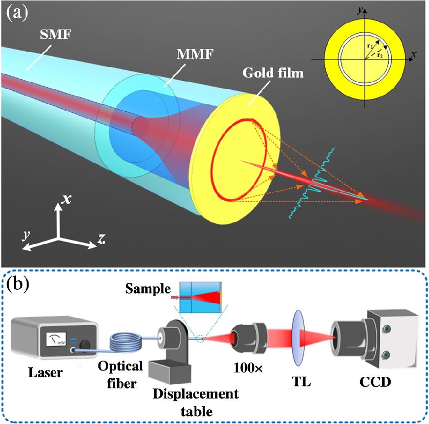
A schematic diagram of our all-fiber IPB generator is shown in Fig. 1. In the generator, one end of a graded index multimode fiber (MMF) with a specific length is fused with a single-mode fiber (SMF); the other end of the MMF is polished and plated with nanogold film, and then surface plasma structure is prepared on the gold film. When the device is working, the optical field radiating from the SMF is first expanded in the MMF and subsequently irradiates the plasma structure to excite plasmon waves; then the excited plasmon waves will couple into the free space via the plasma structure and produce the subwavelength IPB. In this scheme, expanding the optical field using the MMF aims to provide more space for the flexible design of the plasma structures. In Fig. 1(a), the plasma structure illustrated is a nanoring slot with inner radius and external radius being and , respectively. Figure 1(b) shows the schematic diagram of the measurement system for measuring the far-field transversal optical intensity distributions generated by the fiber plasma structure. The single-wavelength laser is coupled into the IPB generator through an SMF, and the imaging system is a Nikon microscope that consists of a 100× objective lens with , a tube lens (TL), and a charge-coupled device (CCD) with a single pixel . The IPB generator is fixed on a high-precision displacement table. During the movement of the displacement table, the imaging system can observe the far-field intensity distribution of the IPB with different propagation distances.
![]()
Figure 1.(a) 3D schematic diagram of the all-fiber far-field IPB generator. SMF is a single-mode fiber and MMF is a graded index multimode fiber.
Assuming that is the mode field distribution function at the output face of the MMF (i.e., plane) and is the aperture function of the plasma structure, according to the Rayleigh–Sommerfeld diffraction formula, the output optical field can be expressed as
Considering that the center of the nanoring slot is located on the central axis of the MMF, and the width of the slot is much smaller than the wavelength, i.e., , the aperture function can be rewritten as
![]()
Figure 2.Normalized intensity distributions of the output optical field simulated via the analytic equation. (a) Normalized intensity distribution in the
2.2 Experimental Generation of IPB via Nanoring Slot
As shown in Fig. 1, the optical field needs to be expanded to provide more space to design the structure. For the nanoring slot structure with an inner radius of , if the optical field is not expanded via MMF, the radius of the mode field in the SMF core should be much less than , which means that the structure cannot be illuminated at all. Therefore, the length of the fused MMF will affect the far-field distribution of the output light. We calculate the optimal fusion length of the MMF by Rsoft simulation. The SMF and the MMF selected in the simulation are the Coherent 980-xp SMF (Coherent Company) and OM1 graded refractive index MMF (Yangtze Optical Fibre and Cable Joint Stock Limited Company), respectively. The simulation results are displayed in Fig. 3. Figure 3(a) is the normalized intensity distribution of the optical field in the plane when the light is coupled from the SMF to the MMF, from which we can see that fusing a long MMF to the SMF can achieve an optimal beam expansion. Figures 3(b) and 3(c) are the normalized intensity distributions of the optical field on the plane and along the axis after being expanded by the long MMF. The blue curve in Fig. 3(c) is the simulation result extracted from Fig. 3(b).
![]()
Figure 3.Normalized intensity distributions of the optical field of the MMF. (a) Normalized intensity distribution on the
Based on the simulation results, we fused a long MMF to the SMF and polish the end surface of the MMF. Then we measured the normalized intensity distribution of the optical field along the axis; the experimental result is shown as the red curve in Fig. 3(c). It can be seen that the experimental result is highly consistent with the simulation result, and the optical field follows Gaussian distribution with an FWHM of . The surface morphology of the MMF end surface, as shown in Fig. 4(a), is measured using a 3D morphometer microscope (sneox-IFU90). By extracting the surface height distribution in the horizontal direction of the MMF end surface, it can be seen that the surface height drop is only 20 nm in the center region of the MMF end surface with a diameter, as shown in Fig. 4(b), which is suitable for processing plasma structures. The scanning electron microscope (SEM) image of the fabricated nanoring slot with and is shown in Fig. 4(c).
![]()
Figure 4.Sample characterization. (a) 3D morphology measurement result of the polished fiber end surface. (b) Morphology measurement results along the
In the experiment, a 980-nm wavelength laser is selected as the incident light. During the measurement process, the all-fiber IPB generator is fixed on an electronically controlled nanodisplacement table, and the fiber end surface is defined as the original plane (). The nanodisplacement table is used to move the end surface of the subwavelength beam generator with a precision of 200 nm step by step, so the intensity distribution of the output optical field at different transmission distances can be observed and recorded experimentally. Figures 5(a1)–5(a4) show the observed light-intensity distributions on the plane at different distances (4, 5, 6, and ) from the fiber end surface. Then the intensity distributions along the axis of the four corresponding planes are extracted from Figs. 5(a1)–5(a4) and compared with the simulation results, as shown in Figs. 5(b1)–5(b4), where the red curves are the experimental results and the blue curves are the simulation ones. The FWHM of the experimental results are 378 nm (), 428 nm (), 450 nm (), and 504 nm (), respectively. Therefore, the generated optical field with subwavelength resolution () when the propagation distance is fits well with the theory. Meanwhile, we extract the light-intensity distributions along the axis of different transmission distances in the range of with 200 nm step precision, and then splice the extracted results to obtain the intensity evolution of the light along the propagation direction, as shown in Fig. 5(c). It clearly reveals that the output light generated by the plasma nanoring slot is an IPB, and the intensity evolution is in high agreement with the simulation result shown in Fig. 2(a). Figure 5(d) shows the simulation and experimental results of the FWHM of the main lobe of the IPB at different transmission distances. It can be seen that the FWHM obtained from experimental measurements increases with the propagation distance, and the FWHM of the IPB is smaller than under . This trend is consistent with the simulation results. However, the FWHMs of the experimental results is slightly larger than that of the simulation results, which may be due to imperfections in the device fabrication process.
![]()
Figure 5.(a1)–(a4) Observed intensity distributions of the output light on the
We further find that the FWHM remains subwavelength-scale, even though the propagation distance from the fiber end surface reaches . This makes the beam ideal for realizing noninvasive single-point illumination or targeted stimulation of subcellular structures inside a living cell, such as organelles, biomolecules, or nanosized pharmaceutical particles, thus allowing for the study of relevant life processes at the single-cell level through light–matter interactions on a subwavelength scale. It should be noted that, however, the above experimental results are obtained in the air environment. Usually, cells can only survive in liquid environments such as cell culture fluid, blood, and biological tissue fluid. Therefore, it is necessary to study the output optical field of our all-fiber IPB generator in a liquid environment. However, due to the lack of a water immersion objective, we do not have the experimental conditions to measure the intensity distribution of the output optical field when the device is placed in a liquid environment. Fortunately, the correctness of the theoretical formula (1) is fully proven by the fact that the experimental results are in good agreement with the simulation results when the device is placed in the air environment. Therefore, we can also effectively evaluate the transmission evolution of the output light theoretically when the generator is placed in a liquid environment. For this, the variations of the FWHM of the main lobe with the transmission distance when the device is placed in blood serum and glycerol solutions were simulated, respectively. The simulation results are shown as the green and orange solid lines in Fig. 5(d). In the simulation, the refractive index of glycerol and blood serum solutions are chosen to be 1.473 and 1.344.39 It can be seen that by placing the device in a medium with a refractive index greater than that of air, such as blood serum and glycerol, the FWHM of the IPB will be further reduced, and even if the transmission distance reaches , the FWHM will still be smaller than half of the wavelength, so it is expected to achieve light–matter interactions in a living cell with higher precision. Moreover, in order to evaluate the influence of the transmission loss of the blood serum environment on the evolution of the IPB beam, we calculated the evolution of the normalized intensity on the center axis of the IPB beam during its propagation in a blood serum environment with different absorption coefficients ; the simulation results are shown in Fig. 7(e). It can be seen that since the distance of the optical field propagation is only at a 10 mm scale, the effect of loss on the intensity evolution is negligible.
2.3 Generation of Subwavelength Beam with Sidelobe Suppression Characteristic
Although it has been demonstrated that the fiber end integrated nanoring slot can generate an IPB with subwavelength resolution effectually, the obtained IPB is accompanied by strong sidelobes, which may limit its field of view and, hence, potential applications. Suppressing the strong sidelobes can overcome this deficiency. For sidelobe suppression, Hu et al.40 have proposed a sharp-edge diffraction element consisting of a pair of moonlike sharp-edged apertures, which can generate an optical superoscillation with low sidelobe in a particular dimension. Motivated by this, we designed and fabricated a nanopetal plasma structure structure on the end surface of the fiber to produce a subwavelength beam with sidelobes suppressed in two dimensions. The design process of the nanopetal structure is depicted in Fig. 6(a). Initially, the central axis of the fiber is considered as the center of the circles and with radii and , respectively. Then, the circles , , , and are obtained by shifting along the negative axis, positive axis, positive axis, and negative axis with the displacement ; finally, the gold film in the parts of circles , , , and that do not intersect with circle are etched off to form the nanopetal structure. The aperture function of this nanopetal structure is
![]()
Figure 6.(a) Schematic of the nanopetal structure etched on the fiber end surface. (b) SEM image of the nanopetal plasma structure. (c) and (d) Simulation and experimental results of the optical intensity distribution with a propagation distance of
The SEM image of the nanopetal structure etched on the fiber end surface is presented in Fig. 6(b). Figures 6(c) and 6(d) illustrate the simulation and experimental intensity distribution of the output light of the nanopetal structure with a transmission distance of from the fiber end surfaces, i.e., . The results clearly show that it can effectively suppress the sidelobes of the output field in two dimensions, i.e., in both the -axis and -axis directions.
To evaluate the generated subwavelength beam with sidelobe suppression in more detail, we first experimentally measure the output light-intensity distributions along the axis with transmission distances of 4, 5, 6, and from the end surface of the fiber and compare them with theoretical simulation results. The comparison results are shown in Fig. 7. It can be seen that the FWHMs of the main lobe are 407 nm (), 411 nm (), 516 nm (), and 529 nm () at 4, 5, 6, and , respectively. It can be found that before , the FWHM of the generated IPB is smaller than half of the wavelength.
![]()
Figure 7.Normalized intensity distributions along the
Then to provide a clear demonstration of the sidelobe suppression effect of the nanopetal structure on the -axis direction, we extracted the ratio between the maximum intensity of the first-order sidelobe and the maximum intensity of the main lobe from the light-intensity distributions along the axis. The extracted results of the output IPBs from both the nanoring slot and nanopetal structures are shown in Figs. 7(e) and 7(f), in which Fig. 7(e) is the result obtained via theoretical simulation and Fig. 7(f) is the result extracted from the experimental results. The simulation results show that within the range of , the ratio of the output beam of the nanopetal structure is smaller than that of the nanoring slot along the axis. Especially at the distance of , the ratio of the output beam of the nanopetal structure decreases to 8%, implying that the nanopetal structure has a significant sidelobe suppression effect along the axis. The experimental results can demonstrate the sidelobe suppression effect of the nanopetal structure in the same transmission distance range. However, both the output beams of the nanopetal and the nanoring slot exhibit higher experimental sidelobe strengths compared to the simulated results. This discrepancy may be attributed to imperfections in the device preparation process. Nevertheless, these imperfections do not prevent the ability of the nanopetal structure to suppress the sidelobes in the -axis direction. Since for the output beam of the nanopetal structure, the maximum intensity of the first-order sidelobe locates on the 45-deg axis, we further investigated the ratio between the maximum intensity of the first-order sidelobe and the maximum intensity of the main lobe from the light-intensity distributions along the 45-deg axis, and show the theoretical and experimental results in Figs. 7(e) and 7(f). It is shown that on the 45-deg axis, the ratio of the output beam of the nanopetal structure is larger than that of the nanoring slot. This implies that the sidelobe suppression effect of the nanopetal structure in the -axis direction comes at the expense of sidelobe enhancement in the 45-deg-axis direction.
3 Discussion and Conclusion
In the above, we have demonstrated how to generate subwavelength IPB using fiber end integrated plasma structure in detail. The main lobe of the IPB generated by the nanoring slot can retain its FWHM at subwavelength over a propagation distance of , and the subwavelength beam generated by the nanopetal structure can exhibit sidelobe suppression characteristics. These allow the beam to be used for noninvasive illumination or directional stimulation of subcellular structures, such as organelles and biomolecules inside living cells for biological applications, such as high-resolution imaging and light–matter interaction research in a single cell. It, therefore, can provide a compact fiber-integrated solution for studying life processes at the single-cell level, which may be important and promising in future biological and medical research.
Nevertheless, the all-fiber subwavelength IPB generator proposed in this paper still has some aspects worthy of further study. First, comparing the simulation results with the experimental results of the light-intensity distributions of the subwavelength beams generated both by the nanoring slot and the nanopetal structure, i.e., the results of Figs. 5(b1)–5(b4) and Figs. 7(a)–7(d), it can be found that although the intensity distributions of the main lobes obtained from the experimental measurement match well with the simulation results, the sidelobe intensities obtained from the experimental measurement are larger than those of the simulation results, and the experimental results do not have left-right symmetry. Multiple factors may contribute to this phenomenon. For example, it may be because there exists an offset between the center of the plasma structure and that of the output optical field of MMF fiber, which may be caused by the inherent off-axis amount of the fiber core or the fact that the center of the plasma structure is not aligned with the central axis of the fiber in the fabrication. It can also be caused by the 3D roughness of the polished fiber end surface [e.g., slight left-right asymmetry can be seen in Fig. 4(b)], which will make the etched depths of the plasma structure without strict symmetry, resulting in an asymmetry excitation efficiency. Therefore, when considering fabrication error, how to design a plasma structure with higher error tolerance to obtain higher-quality IPB is worthy of further study. Second, the subwavelength IPB generator designed in this paper can only generate a single IPB. In the future, designing a variety of novel plasma structures to generate more diverse structured light fields at the fiber end, such as composite beams containing multiple subwavelength IPBs, chiral beams, and vector beams, may promote the realization of more flexible biological applications of the fiber end optical field.
Biographies of the authors are not available.

Set citation alerts for the article
Please enter your email address
© Copyright 2018-2021 | Chinese Laser Press. All Rights Reserved 沪ICP备15018463号-20