• Chinese Optics Letters
  • Vol. 13, Issue Suppl., S20603 (2015)
Yuan Hu1、2、*, Huilin Jiang2、**, Shoufeng Tong2, Lizhong Zhang2, and Dewen Cheng1
Author Affiliations
  • 1Beijing Engineering Research Center of Mixed Reality and Advanced Display, School of Optoelectronics, Beijing Institute of Technology, Beijing 100081, China
  • 2National Defence Key Laboratory of Air to Ground Laser Communication, Changchun University of Science and Technology, Changchun 130022, China
  • show less
    DOI: 10.3788/COL201513.S20603 Cite this Article Set citation alerts
    Yuan Hu, Huilin Jiang, Shoufeng Tong, Lizhong Zhang, Dewen Cheng. Magnification of divergence angle in a ground test of space laser communication[J]. Chinese Optics Letters, 2015, 13(Suppl.): S20603 Copy Citation Text show less
    Optical principle diagram of the magnification method by a zero-power optical module (a) Inside and (b) outside.
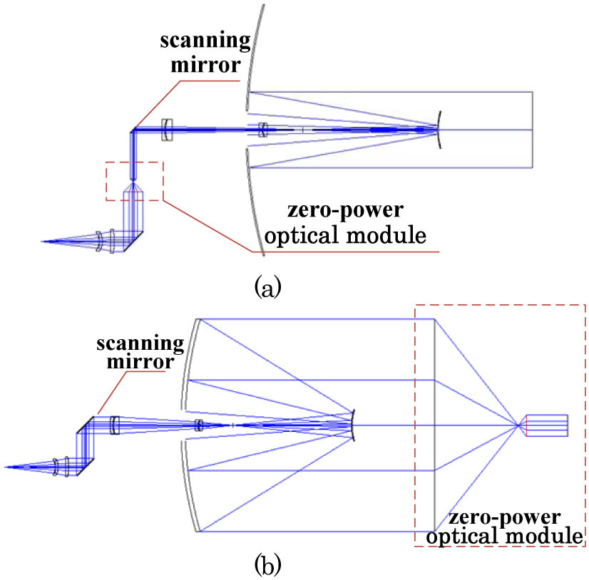
    Fig. 1. Optical principle diagram of the magnification method by a zero-power optical module (a) Inside and (b) outside.
    Given the atmospheric turbulence and platform vibration, the receiving terminal is randomly located at different positions of the emission light spot.
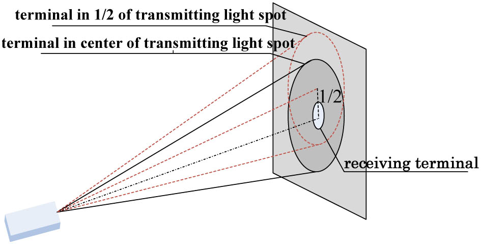
    Fig. 2. Given the atmospheric turbulence and platform vibration, the receiving terminal is randomly located at different positions of the emission light spot.
    Light intensity distribution in the focal plane of the receiver by the defocusing method at: (a) the center of the transmitting light spot and (b) 1/2 of the transmitting light spot.
    Fig. 3. Light intensity distribution in the focal plane of the receiver by the defocusing method at: (a) the center of the transmitting light spot and (b) 1/2 of the transmitting light spot.
    Light intensity distribution in the focal plane of the receiver by the magnification method at: (a) the center of the transmitting light spot and (b) 1/2 of the transmitting light spot.
    Fig. 4. Light intensity distribution in the focal plane of the receiver by the magnification method at: (a) the center of the transmitting light spot and (b) 1/2 of the transmitting light spot.
    Efficiency of the coherent receiving with different methods at different receiving positions.
    Fig. 5. Efficiency of the coherent receiving with different methods at different receiving positions.
    Structural diagram of the divergence angle switching system.
    Fig. 6. Structural diagram of the divergence angle switching system.
    Light spot in the tracking detector at different communication distances.
    Fig. 7. Light spot in the tracking detector at different communication distances.
    Yuan Hu, Huilin Jiang, Shoufeng Tong, Lizhong Zhang, Dewen Cheng. Magnification of divergence angle in a ground test of space laser communication[J]. Chinese Optics Letters, 2015, 13(Suppl.): S20603
    Download Citation