• Chinese Optics Letters
  • Vol. 13, Issue Suppl., S20603 (2015)
Yuan Hu1、2、*, Huilin Jiang2、**, Shoufeng Tong2, Lizhong Zhang2, and Dewen Cheng1
Author Affiliations
  • 1Beijing Engineering Research Center of Mixed Reality and Advanced Display, School of Optoelectronics, Beijing Institute of Technology, Beijing 100081, China
  • 2National Defence Key Laboratory of Air to Ground Laser Communication, Changchun University of Science and Technology, Changchun 130022, China
  • show less
    DOI: 10.3788/COL201513.S20603 Cite this Article Set citation alerts
    Yuan Hu, Huilin Jiang, Shoufeng Tong, Lizhong Zhang, Dewen Cheng. Magnification of divergence angle in a ground test of space laser communication[J]. Chinese Optics Letters, 2015, 13(Suppl.): S20603 Copy Citation Text show less

    Abstract

    For a long communication distance, the divergence angle of laser transmission by a space laser communication system must be sufficiently narrow to solve the energy problem. However, it needs to be magnified during the ground test before the satellite launches. This way, the two communication terminals can be constantly in the coverage of each other’s laser beam even when the tracking accuracy decreases because of the atmosphere. This Letter presents methods to magnify the divergence angle for laser transmission. The diffraction intensity distributions with different methods and their influence on communication are discussed. We provide the optimal scheme in the ground test of a certain space laser communication. The result represents the accumulated experience for the space laser communication ground test.

    Ground tests represent a key process for verifying the performance of space laser communication terminals before they are loaded on space platforms[14]. However, due to the variation of link distances, a huge difference will always exist in the requirement of laser communication systems, especially the divergence angle of the laser beam emitted by the terminal. The design of the divergence angle should consider system energy, scanning strategy, tracking accuracy, communication distance, and other factors. The divergence angle is usually very small to ensure energy efficiency in a long-distance link. However, the link distance is not as long in the ground tests and the tracking precision significantly decreases because of atmospheric influences[58]. Therefore, an extremely narrow divergence angle can hardly ensure that the two communication terminals are always in the coverage of each other’s laser beam. Therefore, transforming the size of the divergence angle is necessary to adapt to the near-ground link. The original space laser communication terminal may not be directly used in the ground tests, but only after some modifications. Hence, the primary challenge is to match the parameters with the communication link while ensuring the integrity and stability of the terminals.

    This Letter provides two methods to magnify the divergence angle of the laser beam transmission by a laser communication optical system. The engineering feasibility is also analyzed. Furthermore, the diffraction intensity distributions on the focal plane under different methods are compared and the influence on coherent communication is discussed. The ground test of a certain space laser communication terminal is introduced.

    A typical space laser communication terminal is composed of one Cassegrain optical antenna and several optical subsystems[9,10]. A parallel light path is adopted for their connections. Two commonly used techniques can be used to magnify the beam divergence angle: the magnification method and the defocusing method.

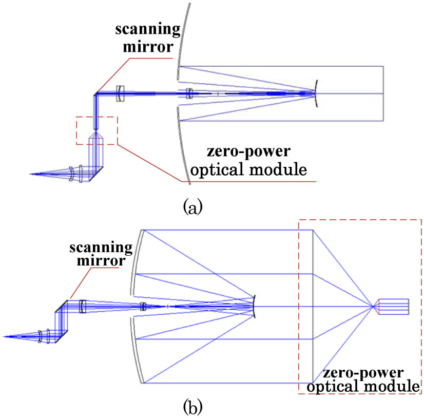
    The magnification method entails using a zero-power optical system with a certain amplification ratio to magnify the divergence angle. The zero-power optical system module is inserted into the parallel light path. According to the theory of geometric optics, the amplification ratio of the divergence angle is inversely proportional to the diameter. As shown in Fig. 1(a), the zero-power module with a fourfold angle amplification ratio is used. Accordingly, the aperture decreases four times. As a result, the obscuration ratio of the optical antenna increases dramatically. Full obscuration may be achieved with the continuous increase of the amplification ratio. The zero-power optical module inside will exhibit the advantages of small volume, light weight, and convenient layout, but also the limitation of large energy loss. If the laser emission system is designed with a zoom form to change the divergence angle, the same principle applies to the magnification method. Thus, the two methods fall under the same category.

    Optical principle diagram of the magnification method by a zero-power optical module (a) Inside and (b) outside.

    Figure 1.Optical principle diagram of the magnification method by a zero-power optical module (a) Inside and (b) outside.

    Another magnification method entails placing the zero-power optical system with a certain amplification ratio outside the optical antenna, as shown in Fig. 1(b). This method is simple and convenient, but it changes the magnification of the optical antenna. An influence will be produced on all laser communication optical subsystems. According to the theory of geometric optics, the focal length of the receiving optical system will be shortened and the field of view will be enlarged with the magnification of the divergence angle. As a consequence, the optical system cannot be matched with the indicators. This result especially affects the acquiring, pointing, and tracking (APT) system. The scanning mirror of the APT system cannot achieve the desired scanning range after the enlargement of the field. Obviously, both the weight and volume of the zero-power optical system with an equal aperture of the optical antenna will be very large. If the zero-power optical system is placed outside the optical system, the force balance of the APT system will be destroyed. Moreover, its large volume makes placement difficult. For this reason, this method has low feasibility in engineering.

    The defocusing method entails moving the light source away from the ideal position to beam divergence. One way is moving the light source away from the ideal position along the optical axis backward and forward. Another method is adding a lens in the optical system to change the focal length. For any of these methods, positive and negative defocusing exists. Beam divergence should be ensured and no convergence spot should be present in the communication link.

    The defocusing method is simpler and does not take up too much space. However, this method needs to be finished during the adjustment. In this process, the fiber light source protection is easily stained and damaged. By applying the lens method in the opposite direction, the structure of the inserted lens will occupy a space that is already too small. However, the modularization operation is easy to implement and is beneficial for the protection of the light source.

    Each method produces a different influence on diffraction at a long distance. Therefore, analyzing the light intensity distribution under different methods is important.

    According to the diffraction theory, the far-field condition is expressed as ZD2/λ, where Z is the communication distance; D is the aperture of the optical antenna, which is 250 mm; λ is 1.55 μm. Thus, Z40km. In the actual link for satellite-to-ground communication, Z is at a magnitude of 10000 km, thereby satisfying the far-field condition. In the space laser communication system, the laser is the light source and is regarded as the Gaussian beam with the TEM00 mode. The amplitude distribution is E=Eoeρ2/ω2, where ρ is the polar coordinate variable in the antenna aperture plane and ω is the waist radius of the Gaussian beam. The light spot shows the Fraunhofer (far field) diffraction distribution in the receiving location as follows[11]: Ei(ρ,θ)=1iλZexp[ik(Z+ρ22Z)]×Eo(ρ,θ)ed2/ω2exp[ikρρZcos(θθ)]ρdρdθ.

    The far-field condition cannot be satisfied in the ground test. Therefore, the light distribution shows the Fresnel (near-field) diffraction as follows: Ei(ρ,θ)=1iλZexp[ik(Z+ρ22Z)]×Eo(ρ,θ)ed2/ω2exp[ik2Zρ2]exp[ikρρZcos(θθ)]ρdρdθ.

    If the divergence angle is magnified by the defocusing method, the wavefront aberration caused by defocusing is expressed as W(ρ,θ)=Wdefocusρ2, where W(ρ,θ) is the optical path difference caused by defocusing, Then, after defocusing, Edefocus(ρ,θ)=Eo(ρ,θ)ed2/ω2exp[ik(Wdefocusρ2D2)].

    Substituting Eqs. (3) into (1) and (2), the near-field and far-field distributions of the laser transmission caused by defocusing are obtained.

    For the magnification method, the divergence angle is magnified η times using a zero-power optical system. At the same time, the aperture D of the antenna decreases by η times. The near-field and far-field distributions in Eqs. (1) and (2) do not change.

    A typical antenna of the space laser communication system belongs to central obscuration. Therefore, the laser beam does not result in circular aperture diffraction, but in annular diffraction. The light intensity distribution can be expressed as the difference between the circular aperture diffraction and central obscuration as Ei=E(a)E(b).where a is the clear aperture and b is the radius of central obscuration.

    A direct detection of space laser communication is sensitive to the effective energy per unit integration time. The influence of different light intensity distributions comprise the variations of the absolute value of energy. Here, deep consideration is not necessary. The coherent detection of space laser communication is extremely sensitive to light intensity distribution. In heterodyne coherent receiving, weak signals are amplified by coherent superposition between the signal beam and the local beam. Such superposition of light intensity can be equivalent to that occurring in the entrance pupil plane of the optical system. In the heterodyne coherent detection system, the coherence efficiency can be expressed as η=|Ei(ρ,θ)Eio*(ρ,θ)ρdρdθ|2Ei2(ρ,θ)ρdρdθEio2(ρ,θ)ρdρdθ,where Ei is the intensity of the signal beam, Eio is the intensity of the local beam, and * is a complex conjugate. The local light source uses a laser, which is a Gaussian beam with the waist located on the focal plane. Hence, Eio=Eoed2/ω2, where d is the receiving aperture and ω is the waist radius of the Gaussian beam. The light intensity distributions with defocusing method and magnification method at different distances within the receiving aperture are shown in Eqs. (1), (2), and (3). They are substituted into Ei in Eq. (5), respectively. Thus, the influence from different methods of magnifying the divergence angle on the coherence efficiency is obtained. A normalization process is needed for the actual calculation.

    The light intensity distribution at a far distance is simulated according to the diffraction theory. The simulation conditions are as follows[12,13]. The single-mode fiber as the light source, 1550 nm wavelength, and the beam regarded as a Gaussian beam.The aperture of the transmitting antenna is 250 mm and the aperture of the ground-based receiver antenna is 650 mm, with both configured as an annular aperture with central obscuration; the obscuration ratio is 1/13.The communication distance in the ground test is 5–20 km.In a medium turbulent atmosphere, the tracking accuracy, terminal performance, communication distance, and energy are comprehensively considered; the divergence angle of the beam in the ground test is set to 500 μrad.In the defocusing method, the angle is changed from 15 to 500 μrad; in the magnification method, the zero-power optical system with a 33.33 magnification is chosen. Under the far-field condition, z36.3m.The emitted light beam shows a random jitter due to the atmospheric turbulence and platform vibration. This means that the receiving terminal at the far distance is randomly located at different positions of the emission light spot, as shown in Fig. 2. Simulations are carried out at the center and 1/2 of the emission light spot.

    Given the atmospheric turbulence and platform vibration, the receiving terminal is randomly located at different positions of the emission light spot.

    Figure 2.Given the atmospheric turbulence and platform vibration, the receiving terminal is randomly located at different positions of the emission light spot.

    Under the above simulation conditions, the light intensity distribution in the focal plane of the receiver is analyzed, as shown in Figs. 3 and 4.

    Light intensity distribution in the focal plane of the receiver by the defocusing method at: (a) the center of the transmitting light spot and (b) 1/2 of the transmitting light spot.

    Figure 3.Light intensity distribution in the focal plane of the receiver by the defocusing method at: (a) the center of the transmitting light spot and (b) 1/2 of the transmitting light spot.

    Light intensity distribution in the focal plane of the receiver by the magnification method at: (a) the center of the transmitting light spot and (b) 1/2 of the transmitting light spot.

    Figure 4.Light intensity distribution in the focal plane of the receiver by the magnification method at: (a) the center of the transmitting light spot and (b) 1/2 of the transmitting light spot.

    Based on Figs. 3 and 4, Fresnel diffraction occurs along the entire communication distance with defocusing method. The center of the light spot shows an alternation between hollow and solid. The intensity periodically oscillates with distance. In the magnification method, the energy is concentrated at the main peak, and the sidelobe energy is weakened. The light intensity is stabilized with distance. Even for marginal positions, the light spot shows a good roundness and energy concentration. In fact, given that the magnification method decreases the transmitting aperture, the far-field condition becomes less strict. Its diffraction changes less significantly with distance and position compared with the defocusing method.

    Then, the efficiency of coherent receiving is analyzed. Assuming the ratio of the beam waist to the aperture is 1 for both the transmitting antenna and the receiving antenna, Figure 5 is obtained as follows.

    Efficiency of the coherent receiving with different methods at different receiving positions.

    Figure 5.Efficiency of the coherent receiving with different methods at different receiving positions.

    Based on Fig. 5, the coherence efficiency of the magnification method is generally higher than that of the defocusing method. At the center and 1/2 of the light spot, the difference in the coherence efficiency decreases. In short distance communication, the magnification of the divergence angle causes a serious decline of the coherence efficiency. With increasing distance, the coherence efficiency increases dramatically. Moreover, the difference between the two methods declines. However, the coherence efficiency under the ideal state cannot reach one even if the communication distance increases infinitely. The reason is that the increase in distance results in a uniform light intensity distribution at the antenna. As the local beam is a Gaussian distribution, the coherence efficiency will never reach one.

    As discussed above, the magnification method can lead to a more uniform light intensity distribution at a long distance, and the receiving efficiency is higher. However, this method has low engineering feasibility in ground tests. Thus, for the ground test of certain space laser communication terminals using direct detection, the defocusing method is employed to magnify the divergence angle.

    In the experiment, the beacon emission light path used the defocusing method for magnifying the divergence angle. The motor-driven insertion of the defocusing lens was performed to flexibly adjust the divergence angle. The structural design is shown in Fig. 6.

    Structural diagram of the divergence angle switching system.

    Figure 6.Structural diagram of the divergence angle switching system.

    To ensure the precision of the optical axis during the switching of the lens, the optimization design principle is as follows: when the defocusing lens is not located on the light path, the originally small divergence angle is used. At this time, the parallelism of the optical axes with other optical subsystems has been calibrated and the precision is very high. When the defocusing lens is inserted into the light path, some tilt in the optical axes occurs. However, the divergence angle is large so the tilt of the optical axes could be neglected.

    The direct detection system was used in the experiment of a space laser communication terminal, so the distribution could only be observed by the measurement of the light spot energy. Figure 7 shows the variations of the light spot in the tracking detector under medium atmospheric turbulence with increasing communication distance.

    Light spot in the tracking detector at different communication distances.

    Figure 7.Light spot in the tracking detector at different communication distances.

    Based on Fig. 7, the light spot shows a dispersion at the communication distance of 5 km. However, because of the strong energy and weak atmospheric influence, the light spot maintains a uniform roundness and energy distribution. The spot converges and diameter size decreases with the increase of the communication distance. As the atmospheric influence is intensified, the light spot distribution shows a greater randomness in terms of vibration. Obviously, a strong atmospheric influence reduces the non-uniformity of the light intensity distribution with increasing distance.

    In conclusion, we determine that the diffraction distribution of the magnification method changes less significantly compared with the defocusing method and has the least impact on space laser communication with coherent detection. However, with the increase of communication distance, the light intensity distribution between the two methods seems to grow closer and the atmospheric influence tends to be greater. Therefore, the advantage of the magnification method is not obvious. Meanwhile, the defocusing method is more easily realized in engineering and has a higher feasibility for magnifying the divergence angle in the ground test of space laser communication.

    If the ground test is performed in high mountains and in the air, the communication distance will be greatly increased. It is easier to obtain a uniform light intensity distribution under such far-field conditions. However, in low atmospheric layers the long communication distance will enhance the atmospheric disturbance. Therefore, in ground tests, comprehensive consideration should be given to a variety of parameters. More efforts shall be exerted to create a favorable experimental environment for the verification of the performance of space laser communication systems.

    Yuan Hu, Huilin Jiang, Shoufeng Tong, Lizhong Zhang, Dewen Cheng. Magnification of divergence angle in a ground test of space laser communication[J]. Chinese Optics Letters, 2015, 13(Suppl.): S20603
    Download Citation